ICE CREAM

Introduction
No one knows exactly when ice cream was first produced. Ancient manuscripts tell us that the Chinese consumed a frozen product made by mixing fruit juice with snow – what we now call water ice. This technique later spread to ancient Greece and Rome, where the upper classes enjoyed the frozen desserts.
After disappearing for several centuries, ice cream in various forms reappeared in Italy during the Middle Ages, probably as a result of Marco Polo's return to Italy in 1295 after spending about 17 years in China, where he had acquired a taste for a frozen dessert based on milk. From Italy, ice cream spread through Europe during the 17th century and remained a luxury product for royalty for a long time.
Industrial ice cream production began in the late 19th century when the first mechanical refrigerators gained ground.
The principle of the ice cream freezer was invented in the 19th century, but it was with the invention of the brine freezer at the beginning of the 20th century and the continuous freezer in 1913 that the foundations of the ice cream industry were laid. The first continuous freezer with a controlled air inlet was installed in 1929, and since then the development of the industry has developed rapidly.
Ice cream categories
Ice cream and related frozen products can be divided into several categories, but as the legislation varies from country to country, these categories should only be considered as guidelines.
The fat content of ice cream typically determines the category it belongs to and must not only exceed a certain amount of fat to qualify as ice cream, but in most cases, the fat should be of dairy origin.
In general, ice cream can be divided into the categories listed in Table 21.1. However, there are large variations and legal aspects that determine ice cream categories.
There are other categories on the market, including soft serve ice cream, milkshakes and slush ice, where the freezing of water is carried out at the point of sale. There are also other categories which can be mentioned, such as frozen yoghurt and dispenser ice cream, but most of these do not differ significantly from the above five main categories.
Ice cream types
The type of ice cream itself is determined by the handling method used to shape the products during production, these include:
- Moulding
Where the ice cream products are filled into a mould. The mould is submerged into a refrigerated brine, and the mould content is frozen. The products are pulled out from the mould, and can then be coated with different coatings. - Filling
Where the ice cream is filled into a container that can be anything from smaller cups to larger containers for catering. Cones, like flat-top cones and ball-top cones, can also be produced using filling technology. Products are hardened to storage temperature, where the products are transferred from the filling line to a hardening tunnel. - Extrusion
Where ice cream products are extruded onto trays which are pulled continuously forward by a chain. The trays are pulled through a hardening tunnel after which the products are collected from the trays. They can then be coated with different coatings.
The three different types of handling methods generally affect the quality of the product itself, since a higher proportion of water frozen in the product before shaping provides a higher quality of the ice cream. Since moulding and filling are both indexed processes, less water can be frozen beforehand, as the higher viscosity from more frozen water results in high-pressure build-ups on the moulding and filling line as a result of opening and closing a filling valve. Conversely, extrusion is a continuous process so pressure does not build up in the line, making it possible to freeze out more water and achieve a higher product quality.
Ice cream texture
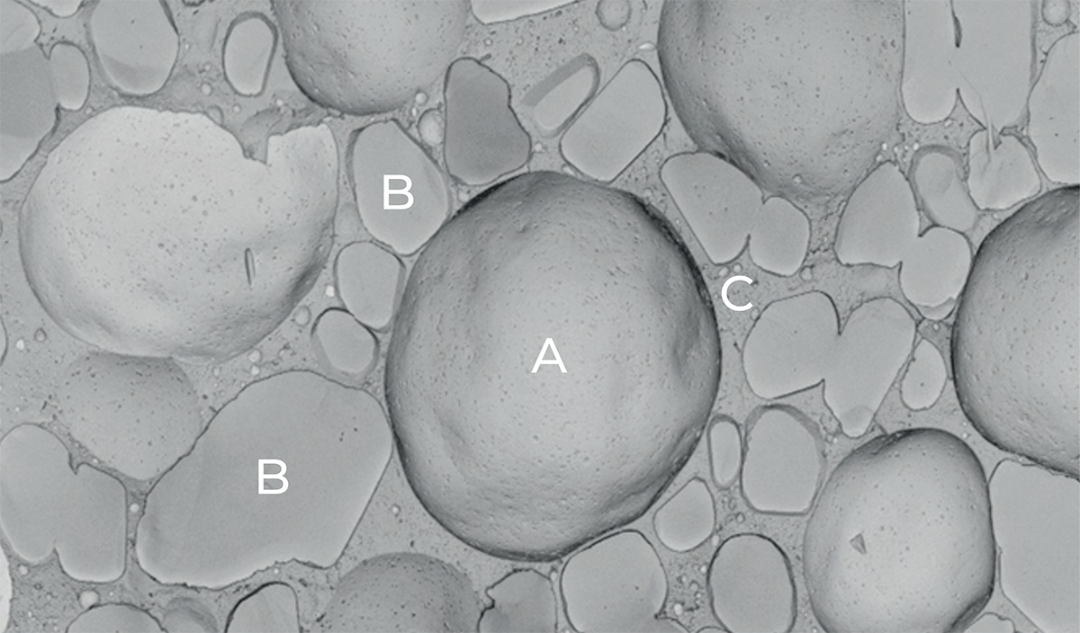
Fig 21.1 Microscope image of ice cream.
(A) Air cell with fat membrane, (B) Ice crystals and (C) Unfrozen phase
Ice cream is a relatively complex food application, as the final ice cream consists of four individual phases, which consist of air, fat, ice crystals and an unfrozen phase.
A standard ice cream contains about 50% air. The air is distributed in the ice cream as small air cells, all of which have a thin membrane of fat that retains the air. These air cells, together with the ice crystals, are dispersed in the unfrozen phase.
During the continuous freezing process, about 50% of the water in the mix is frozen into ice crystals, resulting in a freezing concentration where the concentration of carbohydrates, minerals and proteins becomes so high that the subsequent viscosity of the ice cream is significantly increased. This increase in viscosity affects the mechanical processing during the continuous freezing process, whereby the fat globules churn out and form partial fat agglomerates at the phase transition between air and water. This creates a membrane of partially agglomerated fat on the air cells and creates the ice cream structure.
It is the balance of the four phases that defines the structure of the ice cream. Assuming that the unfrozen phase of the ice cream at serving temperature is proportionally larger, it affects the texture of the finished ice cream by being soft, also referred to as “scoopable”. Conversely, a proportional lower unfrozen phase produces a hard texture at serving temperature. This not only affects the ice cream when serving but also the process of making the ice cream. The balance between the phases is adjusted by changing the freezing point in the unfrozen phase, where a lower freezing point results in a proportionally larger unfrozen phase, which causes a smaller amount of water to freeze into ice crystals.
The fat membrane, which separates air and the unfrozen phase, is made up of partially agglomerated fat. It is technically the strength of this membrane that determines whether an ice cream changes structure during processing and storage. Therefore, it is essential for ice cream production that the fat is treated in the right way. Through the ice cream mix processing, the fat is prepared to form the partial agglomeration that creates the air cell membrane.
Ingredients for ice cream
The quality of an ice cream depends on both the type and composition of the ingredients.
Fat
Fat makes up about 4 – 15% of an ice cream mix and can originate from dairy or vegetable sources. Fat improves the melting resistance by stabilising the air cell structure of the finished ice cream and provides consistency and taste.
Dairy fat is used in the form of whole milk powder, cream, butter or anhydrous milk fat (AMF). It can be replaced by vegetable fat, most often coconut or palm kernel oil.
If vegetable fat is utilised, then it is essential that the fat can re-crystallise, i.e. go from liquid to solid form during the ageing process. Solid fat is important during the continuous freezing process, where it can partially agglomerate to create the air cell membrane.
Milk solids non-fat
Milk solids non-fat (MSNF) is milk where water and fat are removed, and consists of proteins, lactose and mineral salts.
To ensure a balanced ice cream mix formulation, the ratio between milk solids non-fat and water can be calculated.
This ratio is referred to as the MSNF factor and is widely utilised in the ice cream industry to both optimise and troubleshoot the mix formulation.

Formula 21.1
In the ice cream industry, it is generally accepted that this factor should be 17 in order to have a balanced ice cream mix. However, the MSNF factor is by definition independent of the MSNF type and composition, and in the case of non-traditional MSNF types, consideration should be given to calculating MSNF addition based on protein types and amounts.
MSNF accounts for a high part of the raw material costs in an ice cream mix, which is why the MSNF factor also has an economic impact. However, changing the MSNF level changes both sensory performance and poses challenges for processing.
The MSNF level impacts sensory performance, where a low MSNF factor (below about 12) results in a thin mouthfeel and lack of dairy flavour. Furthermore, a lower level of dairy proteins causes less churning during the continuous freezing process, as the lack of water binding from the proteins results in a product that melts faster and thus gives a cold mouthfeel when the ice cream melts quickly during consumption. Less water binding from the proteins can also affect the continuous freezing process, where the overly fast freezing of water during continuous freezing can lead to the generation of an ice layer inside the cylinder, causing the scraper knives to skate. There is a risk that the ice layer will increase until the scraper knives cut into it, causing the continuous freezer to stop completely and require defrosting.
A high MSNF Factor provides a rich dairy flavour, which translates into the perception of a premium ice cream product. However, a high MSNF Factor can also cause crystallisation of the lactose. Under normal circumstances, lactose does not crystallise, but if the concentration of dissolved lactose is too high, there is a risk of crystals forming. This crystallisation occurs only slowly at normal storage temperature, but if the storage temperature of ice cream is exposed to changes through storage and distribution (heat shock), there is a risk of lactose crystal formation. As the lactose crystals are difficult to dissolve in water, then their presence in ice cream is expressed in a sandy sensation that can linger in the mouth.
A high MSNF Factor also causes higher water binding of dairy proteins, which in turn results in a higher viscosity of the mix. This higher viscosity influences other parts of the process. It can be challenging during the cooling sequence in a plate heat exchanger, as well as in the continuous freezing process, where there is a risk of increased churning.
Sugars/carbohydrates
Carbohydrates and other sugars are added to the ice cream mix to increase the dry matter content and provide the sweetness that is preferred during consumption.
Carbohydrates is the common term for saccharides. They are divided into different groups depending on their function in the formulation of the ice cream mix.
- Monosaccharides, i.e. dextrose/glucose and fructose
- Disaccharides, i.e. sucrose and lactose
- Various starch derivates, i.e. glucose syrup and fructose syrup
- Polyols, i.e. glycerol, sorbitol, xylitol and lactitol
- Bulking agents, i.e. polydextrose, inulin and maltodextrin
Table 3 illustrates the relative sweetness (Rel S) of different ingredients used for ice cream. The relative sweetness of all ingredients is related to sucrose (sugar) which is defined as having 1.0, where a higher value in one results in a higher sweetness at the same dosage. This means that it takes 1.9 times more sucrose (sugar) to give the same sweetness as 1.0 times fructose.
The table also illustrates the freezing point depression Factor (FPDF). The freezing point depression of all ingredients is related to sucrose (sugar) which is defined as having 1.0, where a higher value in one results in a higher depression of the freezing point at the same dosage. This means that, for example, it takes 1.7 times more sucrose (sugar) to give the same freezing point depression as 1.0 times fructose. Conversely, 0.3 times less sucrose (sugar) is needed to achieve the same freezing point depression as 1.0 times glucose syrup 42DE.
Calculating the relative sweetness for an ice cream mix requires the relative sweetness of each ingredient to be multiplied by the added dosage of the ingredient and added together to achieve the combined relative sweetness. The same procedure is used for calculating the freezing point depression factor.
In example 2 (SOFT), 2.0% sucrose is replaced by 2.5% glycerol which has a higher freezing point depression factor than sucrose. If the two examples are compared, it is observed that both have the same combined relative sweetness of 12.9, which indicates that the two ice creams have approximately the same sensory sweetness.
The freezing point depression factor changes significantly between the two examples, where example 1 (HARD) is firm and hard at a serving temperature of –18 °C, while example 2 (SOFT), is scoopable at a serving temperature of –18 °C. The difference between the two products is found in the amount of water frozen at serving temperature, where the ice crystal phase is larger in example 1 (HARD) compared to example 2 (SOFT).
The difference between hard and soft ice cream has a significant impact on the process. A soft type (FPDF < 12) can cause problems during the continuous freezing process, whereas too fast freezing of water during continuous freezing can lead to the generation of an ice layer inside the cylinder, causing the scraper knives to skate. There is a risk that the ice layer builds up until the scraper knives cut into it (possibly causing the continuous freezer to stop completely) necessitating a defrosting of the freezer.
If the combined freezing point depression factor is high (hard ice cream), then the product becomes relatively unstable due to heat shock (fluctuating temperatures during storage/distribution), as the amount of water frozen into ice crystals is low. This results in larger ice crystals as the smallest crystals melt and disappear and the products risk becoming icy.
A high combined freezing point depression factor provides challenges during the continuous freezing process, where a lower cream temperature is needed to freeze out the correct amount of water in the ice cream. If an insufficient amount of water is frozen during the continuous freezing process, the viscosity inside the cylinder decreases and interferes with the churning of the fat. If a lower amount of fat is churned, air cell membranes cannot be created or will be fairly weak, and fail to generate the ice cream microstructure.
Emulsifiers
Emulsifiers are substances that help emulsification by reducing the surface tension between the two phases. There are several different types of emulsifiers used in ice cream production, but the dominant and probably most effective emulsifiers for ice cream are mono- and diglycerides of fatty acids (E471).
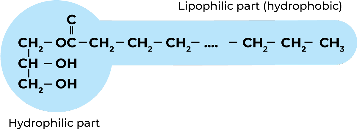
Fig 21.2 Mono- and/ diglyceride of fatty acids
Mono- and diglycerides of fatty acids are produced from a vegetable oil/fat product (triglyceride), where one or two of the fatty acids on the glycerol are removed. This results in a molecule that has a lipophilic (“fat-loving”) part and a hydrophilic (“water-loving”) part, creating a molecule that can act as a link between fat and water, thereby making an emulsion of fat-in-water.
Mono- and diglycerides have two main functions in ice cream processing. On the one hand, they facilitate the re-crystallisation of dairy or vegetable fat during the ageing process. On the other hand, they assist in displacing the dairy proteins from the fat surface membrane.
The functionality of the mono- and diglycerides depends on which vegetable oil/fat they are produced from. For example, sunflower and rapeseed oil result in unsaturated fatty acid chains in the lipophilic part of the molecule. This greatly affects their functionality, where the unsaturated mono- and diglycerides have much higher efficiency in relation to the re-crystallisation and displacement of the dairy proteins during ageing. This is an advantage for the ice cream product but can cause process challenges in both the ageing process and during the continuous freezing process.
Egg yolk is used as an emulsifier in ice cream but is more expensive and less effective than mono- and diglycerides. However, egg yolks are used in products that focus on natural ingredients.
Stabilisers/hydrocolloids
The stabilisers have many functions in ice cream application, both during processing and in the finished product, including:
- Preventing phase separation during ageing
- Binding water in the ice cream mix, which helps with: Providing viscosity during the continuous freezing process, i.e. promoting churning of the fat
- Preventing too fast freezing of the water, i.e. lowering the risk of skating
- Preventing adhesion between product and trays during extrusion
- Preventing and reducing ice crystal growth in the final product
- Providing more viscosity in final products, increasing the mouthfeel during consumption
Combining the different stabilisers provides different sensorial appearances and functionalities in the final product; furthermore, many stabilisers have synergistic effects when combined.
Flavours and colours
Taste and colour are essential factors in the consumer’s choice of ice cream and provide opportunities for the manufacturer to put a signature stamp on their products.
Ice cream production
Processing in ice cream making consists of different stages: mixing, pasteurization, homogenization and ageing, as well as further processing in which the ice cream is frozen, shaped and hardened.

Fig 21.3 Stages of ice cream production and further processing
Mixing
The purpose of mixing is to achieve a homogeneous distribution of all raw materials before further processing. The mixing itself is based on creating turbulence that can distribute the dry and wet ingredients efficiently. There are several forms and levels of technology for mixing raw materials into ice cream.
Batch mixing
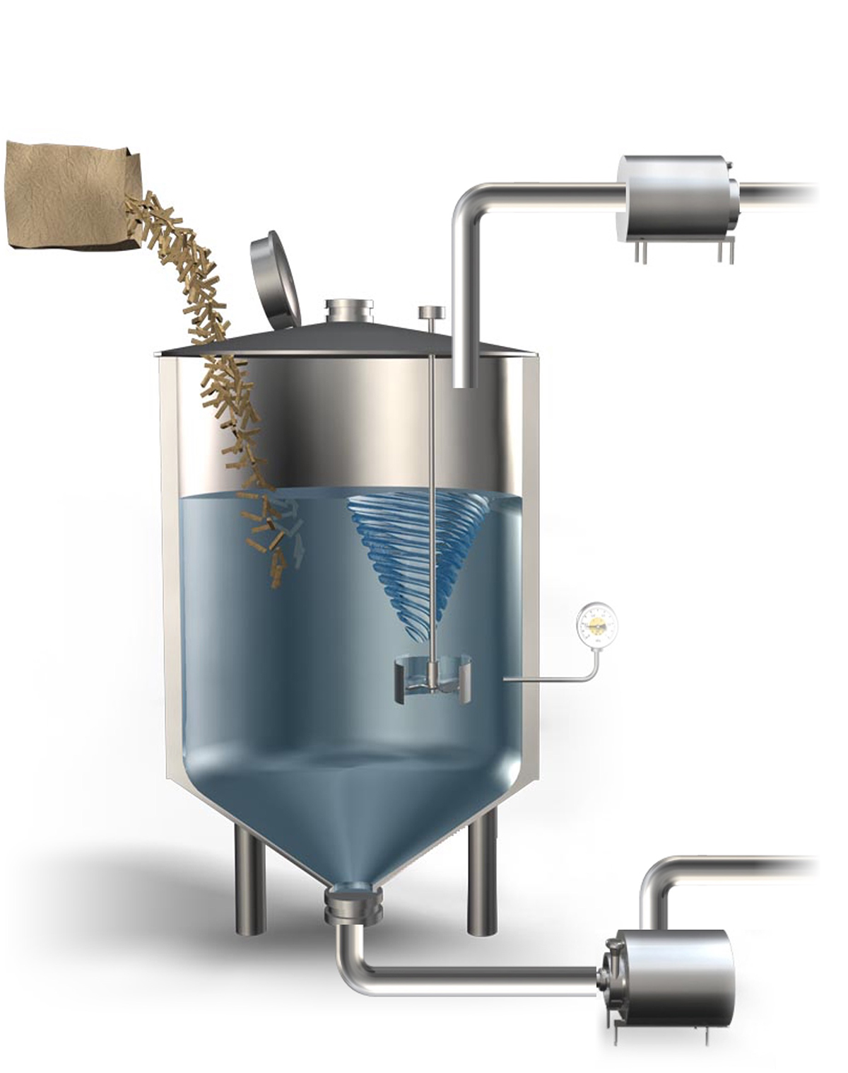
Fig 21.4 Batch mixing tank
Batch mixing is based on a mixing tank that is often equipped with a liquid line for raw materials such as water, milk and cream. Liquid raw materials are usually heated to mixing temperature in a plate heat exchanger before entering the mixing tank.
The mixing tank can be equipped with a heating jacket to either maintain or heat to mixing temperature. The dry raw materials are added manually/ semi-manually through a hatch/manhole, and the stirring device inside the tank mixes the ingredients.
Batch mixing is quite flexible, and because all ingredients are mixed in one batch, there is high traceability. However, this system is vulnerable to human error, where very fast dosing of raw materials or an incorrect mixing protocol can cause challenges.
This type of mixing unit also has a relatively high energy consumption and mixing often takes longer than other inline mixing processes, thereby delaying the production process.
Inline mixing
Inline mixing is based on multiple closed hydration tanks, where the mix recirculates over a powder funnel unit. The hydration tanks are equipped with a liquid line for raw materials such as water, milk and cream. The liquid raw materials are often heated to mixing temperature in a plate heat exchanger before entering the hydration tank. The hydration tank can be equipped with a heating jacket to either maintain or heat to mixing temperature.
The dry ingredients are added to the liquid mix in the powder funnel unit, and the mixing is a result of the mechanical processing that comes through recirculation.
A powder funnel is often replaced with a high-shear mixer, which not only significantly increases the potential speed of adding raw materials, but also minimises air incorporation into the liquid mix. If this is to be avoided altogether, it is possible to install a high-shear mixer with a vacuum, thereby eliminating all air incorporation into the liquid mix.
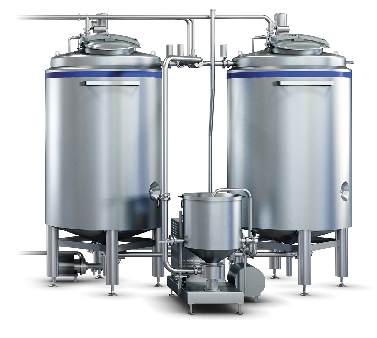
Fig 21.5 Inline mixing with high-shear mixer
Mixing protocol
There are other mixing procedures, but it is recommended to follow these minimum guidelines:
- Whey powder/skimmed milk powder replacers should be added after fat has been added, thereby minimising foaming.
- Emulsifiers and stabilisers should be added as late in the process as possible, and it is also recommended that they are deblended (dry mixed) with sugar to ensure complete dispersion.
Heat treatment/pasteurization
The most common heat treatment in the ice cream industry is continuous pasteurization through a plate heat exchanger (PHE or HTST), where the ice cream mix is heated and cooled over 3 or 5 sections, thereby inactivating pathogenic bacteria. Since ice cream mixes often have a relatively high viscosity, a plate heat exchanger must be designed and optimised for this specific purpose.
The heat treatment takes place over different steps or sections:
- Heating to homogenization temperature (> 75 °C) and homogenization
- Heating to pasteurization temperature (> 80 °C) and holding cell (> 25 seconds)
- Cooling to ageing temperature (< 5 °C)
During heating, raw materials and functional ingredients are also activated.
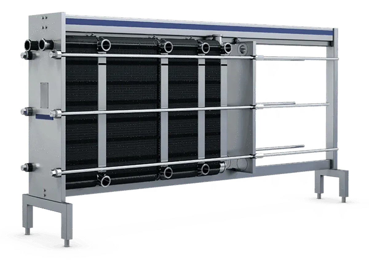
Fig 21.6 Plate heat exchanger
Homogenization
Homogenization is a process where the liquid ice cream mix is put under high pressure and pressed through a narrow opening between a static seat and a counterpart piston, where a high pressure is applied using a hydraulic pressure (50 – 200 bar).
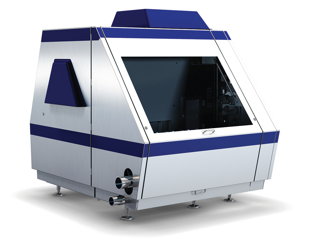
Fig 21.7 Homogenizer
To optimise the fat membrane on the air cell that is built during the continuous freezing and to adapt the protein stabilisation of the fat globules, then the homogenization pressure should be adjusted towards both the type and level of fat level in the mix.
The graph illustrates the pressure range recommended for the first and second stages of homogenizing the mix when using an HD100 homogenization device using three different fat types, i.e. cream, butter and vegetable fat/butter oil. The pressure is indicated for 7 different fat levels in the mix, from 2 – 14% fat.
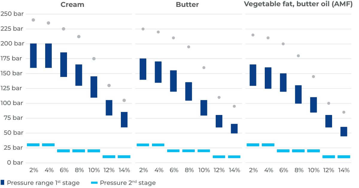
Fig 21.8 Guidelines for homogenization pressure and fat content (using HD100 device)
Ice cream mix unit
Often, the units in the mix processing are combined in a single plant, whereby unified automation and control make the components work together.
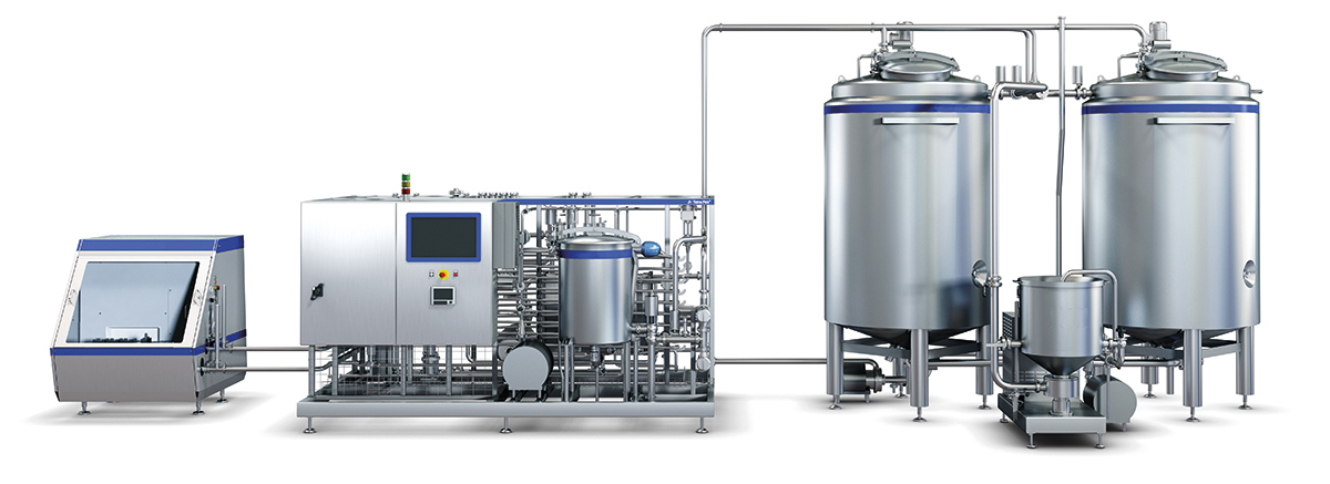
Fig 21.9 Ice cream mix unit
Ageing
Ageing of the ice cream mix is important, as it readies the mix for further handling. During this process, the following processes take place in the ice cream mix:
- Stabilisers are hydrated
- Proteins are hydrated
- Fat globules
- Fat in the fat globules recrystallises
- Dairy proteins are displaced from the fat globule membrane
It is important to let the ice cream mix by stirring it slowly at a temperature below 5 °C for a minimum of 4 hours. During this time, the ice cream mix is prepared for continuous freezing. Insufficient ageing can cause significant challenges in further processing and severe quality defects in the final product.
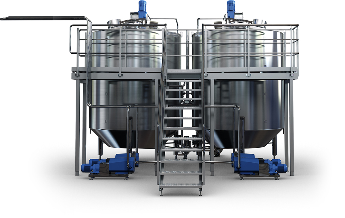
Fig 21.10 Ageing tanks
Hydration of stabilisers and proteins
Stabilisers are ingredients that need hydration before providing functionality, where insufficient ageing leads to lower water binding.
Several different proteins can be used to produce an ice cream including both vegetable and dairy proteins. Most proteins need time to hydrate in order to bind water.
- Insufficient binding of water leads to several processing defects:
- Lack of churning inside the continuous freezer due to lower mix viscosity, leading to lower partial fat agglomeration where the final product would have lower form-stability and melt faster.
- Increased risk for freezing out non-bound water, leading to skating and freeze-out in the freezing process.
- Wet surface on products, leading to increased adhesion for extruded products
- Quality defects in sensory performance in the final product, characterised by a lack of mouthfeel and a colder sensation.
Fat globules
Emulsifiers enter the fat globules during homogenization, facilitating fat re-crystallisation (solidification). The re-crystallisation of fat pushes the emulsifier to the fat surface membrane, where a layer of monoglycerides is formed. The monoglycerides lower the surface tension between fat and water more effectively than the proteins, displacing the proteins from the membrane.
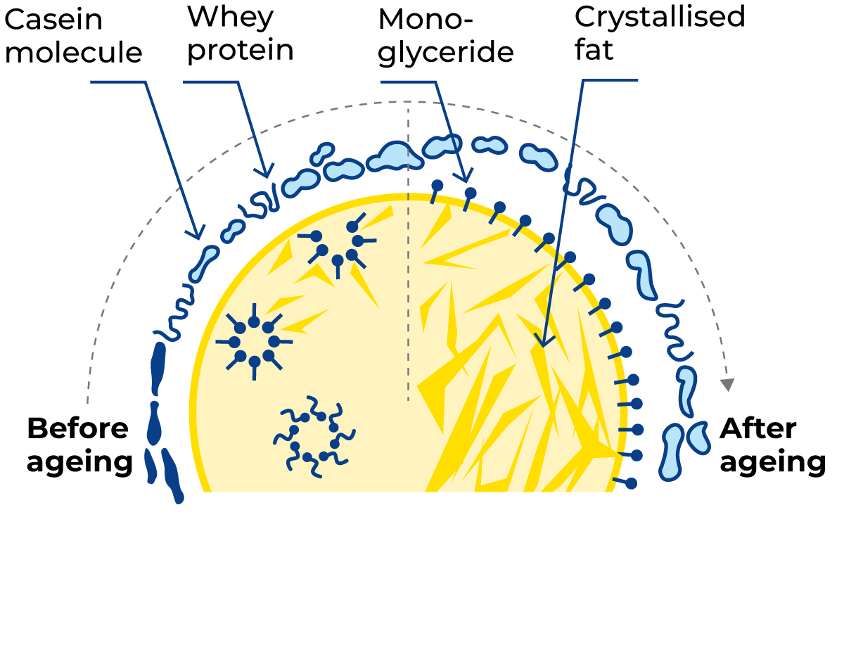
Fig 21.11 The ageing process of fat globules.
Before ageing, fat globules are covered with dairy proteins. During ageing, the emulsifier (monoglyceride) facilitates the re-crystallisation of fats, thereby forcing them to the fat globule membrane, where the dairy proteins are displaced as a result of the monoglycerides lowering the surface tension between fat and water. The re-crystallisation of the fat continues, and at the end of the ageing process, the fat globules have a high level of re-crystallised fat and the fat globule membrane is covered by a monoglyceride layer.
The re-crystallisation of the fat continues, thereby achieving a high level of re-crystallised fat, which enables the later partial agglomeration of the fat globules in the continuous freezer process.
The two processes, re-crystallisation of fat and displacement of proteins, are essential for processing the mix into ice cream and occur during the ageing process. Insufficient ageing leads to the following defects:
- Over-churning of fat in the continuous freezing process
- Failure to achieve overrun (air incorporation)
- Lack of form-stability of products
- Wet/shiny surface of products
- Fast melting products
- Inferior sensorial quality
It is therefore important to comply with the ageing parameters of at least 4 hours at a temperature below 5 °C.
Continuous freezing
The continuous freezing of the ice cream is the core process in ice cream production. It is this process that determines how the entire ice cream processing line performs, and it is therefore important to have the right operation and the right parameters to match the composition of the ice cream mix.
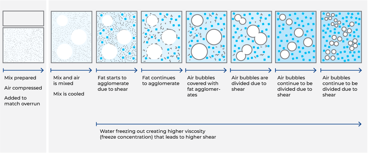
Fig 21.12 Continuous freezing process
The continuous freezer itself consists of a dasher (stirring unit) that rotates and creates mechanical shear for processing the ice cream. The dasher is located inside a cylinder surrounded by a cooling jacket. In this cooling jacket, the refrigerant (ammonia, CO2 or freon) removes energy when it evaporates.
The cylinder is made of a metal alloy that is optimised to transport energy from the process side (inside) to the refrigerant, thus lowering the temperature inside the cylinder when the refrigerant evaporates. When the temperature drops inside the cylinder, the water in the ice cream mix freezes into ice crystals, which form on the surface of the cylinder. The dasher is mounted with scraping knives that scrape off the ice crystals inside the cylinder.
As the water freezes into ice crystals, the concentration of proteins, carbohydrates and added stabilisers in the liquid phase increases (freeze concentration), and viscosity increases accordingly. The higher viscosity increases the mechanical shear, causing the fat globules to partially agglomerate (churn).
The churning of the fat forms a network of partially agglomerated fat globules, which seek the air cellmembranes. When the air cells are covered by a layer of fat globules, they are twisted into smaller air cells by mechanical shear.
After the continuous freezing process, about 50% of the water in the mix is frozen into crystals, and the air (overrun) is encapsulated by partially agglomerated fat globules.
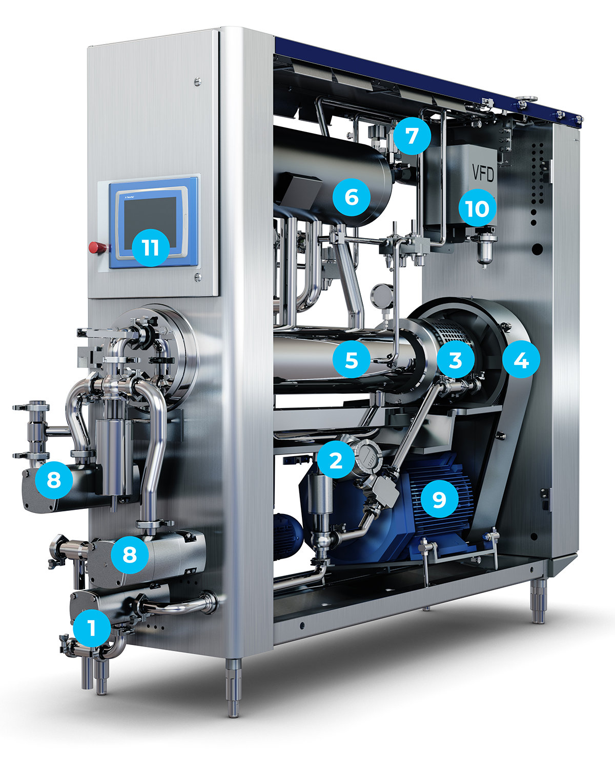
Fig 21.13 Continuous freezer with marking of components described in the text
Below, the components of the continuous freezer, as shown in the image, are described.
1. Mix pump
The mix pump regulates the amount of ice cream mix entering the continuous freezer.
2. Mix flowmeter
The amount of mix is measured volumetrically by the mix flowmeter, which sends feedback to the PLC unit. The PLC unit regulates the mix pump to provide the correct amount of mix to the continuous freezer, thereby ensuring that the selected amount of mix is in accordance with the selected flow.
3. Temperature and pressure gauge
The temperature and pressure of the mix are measured in the inlet pipe to the cylinder. The measured pressure is the pressure inside the cylinder, i.e. cylinder pressure.
4. Air intakes
The air is added to the cylinder through a check valve. The PLC unit regulates the air mass flowmeter to add the correct amount of air in relation to the selected overrun compared to the specific mix flow measured on the mix flowmeter. Overrun is the amount of air that is added proportionally to the mix flow, where an overrun of 100% corresponds to a finished ice cream containing 50% air.
5. Cylinder
The cylinder is made up of four different components:
- Cylinder
- Dasher (agitator)
- Scraping knives
- Beater (stirring blade)
The cylinder is a metal alloy optimised to transport energy from the process side (inside) to the refrigerant, providing optimal cooling of the ice cream during the freezing process. Furthermore, the cylinders are designed to have the largest possible surface area on the cooling side to get the highest utilisation of the cold transport. The inside of the cylinder is chrome-plated for higher wear resistance.
The dasher (stirring device) rotates around inside the cylinder, providing the mechanical shear. The nominal rotation speed is between 230 – 350 rpm and depends on the size of the continuous freezer but can be changed if the continuous freezer is equipped with a variable main motor speed to regulate the mechanical shear.
The scraper knives are loosely mounted on the dasher and scrape the inside of the cylinder wall, thus removing the ice crystals that continuously form as a result of freezing the water.
The beater (stirring blade) is mounted statically in the cylinder, which provides mechanical processing of the product in the cylinder. There are different designs of beaters that can regulate mechanical processing.
6. Cooling system
The cooling system can either be connected to an external cooling system or have its own internal cooling system. Both systems are based on a refrigerant that requires energy for evaporation. This evaporation is controlled differently depending on the two systems and is controlled via the PLC unit.
The cooling system is regulated by two different control loops depending on the product being processed in the continuous freezer.
- Viscosity is measured as the main motor load in percentage. The main motor consumes more energy at increasing viscosity inside the cylinder, and therefore the continuous freezer can be regulated according to the main motor load. If the main motor load is lower than the set value in the PLC, the freezer regulates the cooling system to a lower temperature. Hence more water is frozen and viscosity increases. For a continuous freezer, the set value for the main motor load is expressed as viscosity and correlates to the percentage of the total main motor load. This regulation is applied to most applications.
- Temperature is measured as cream temperature (outlet) in degrees. The cooling system can be regulated according to the cream temperature (outlet temperature). Here the cooling system is regulated towards the cream temperature. This regulation is applied to products where the main motor load (viscosity) is low, i.e. a warm drawing temperature on the cream (outlet).
7. Suction valve
The suction valve controls the cooling system of a continuous freezer with an external cooling system. The suction valve is located between the continuous freezer and the low-pressure side of the cooling system. When the suction valve is opened, evaporated refrigerant is drawn out of the freezer's cooling system (the evaporator), evaporates in the cooling system, and draws energy out of the cylinder.
8. Cream pumps
The cream pump is located at the outlet of the cylinder and controls the pressure in the cylinder.
The cylinder pressure affects the compression of the air in the cylinder. The compression of air increases both the processing time in the cylinder and the contact surface between the ice cream mix and the cylinder, which increases the efficiency of the freezing process.
Furthermore, the cream pump ensures that potential high back pressure from the cream filling lines does not influence the freezing process.
The default cylinder pressure is 4 bars and is normally adjusted proportionally to the overrun, where low overrun requires low cylinder pressure.
9. Main motor
The main motor is connected to the dasher through a belt drive. The main motor speed can be adjusted by either changing the pulleys to get a secondary gearing or – if the freezer is installed with a variable main motor speed (VFD) – adjusted from the operation panel.
10. Variable main motor speed
The main motor can be equipped with a variable frequency drive (VFD) to allow the speed of the dasher to be regulated. Adjusting the dasher speed affects the mechanical shear of the product in the cylinder to optimise the freezing process. Increasing dasher speed provides higher mechanical shear, and thereby higher partial agglomeration of the fat globules (churning), which often results in a stronger and creamier structure of the products. However, an increased rotational speed of the dasher results in more energy provided to the freezing process in the cylinder, which can result in a reduced amount of water freezing in the process.
11. Operation panel
The operation panel or HMI (Human Machine Interface) is used to change and monitor the PLC units. The main parameters that can be changed are:
- Cream flow: The volume of ice cream including air produced
- Overrun: The volume of air supplied proportionally to the mix volume
- Viscosity: Viscosity of the freezing process (load of main motor)
- Cream temperature: Ice cream temperature at exit from the freezing process
- Cylinder pressure: Pressure in the cylinder (compression of air)
- Main motor speed: Rotational speed of dasher
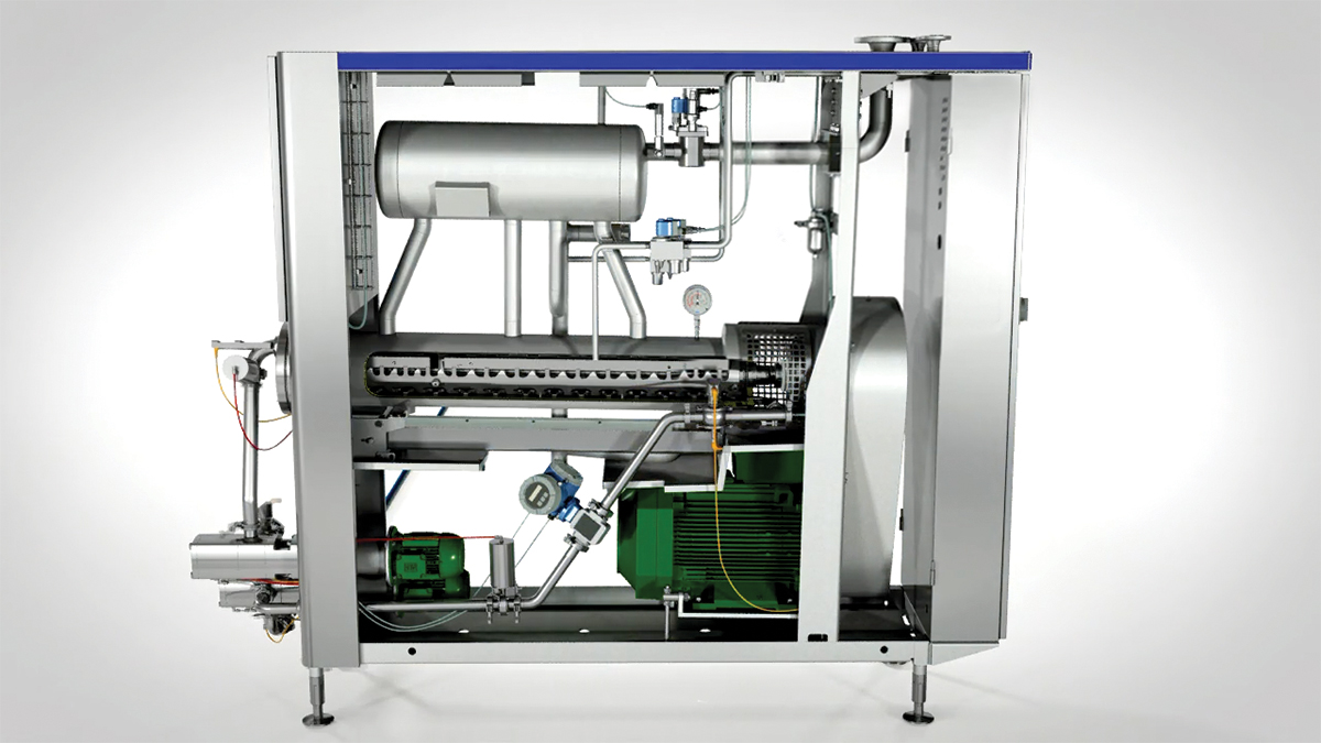
Fig 21.14 Continuous freezer. Dasher with scraping knives placed in cylinders and rotates
Ingredient dosing
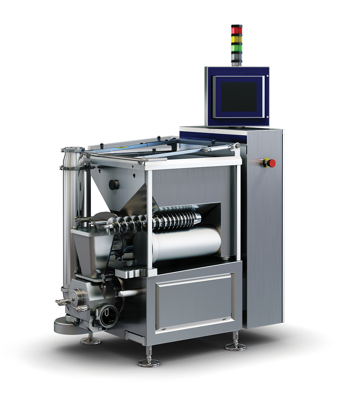
Fig 21.16 Ingredient doser
After the continuous freezing, ingredients can be added to the ice cream before further processing. These ingredients can be of different sizes and types.
An ingredient dosing unit is placed on the process line, where the semi-frozen product from the continuous freezer is mixed with the ingredients.
An ingredient dosing unit can have different degrees of automation. Since the ingredients often have a higher value than the ice cream itself, a higher degree of automation to adjust their addition often makes sense, as this ensures a lower overfill of ingredients.
The ingredients are added to the hopper where the agitator ensures both an even level of ingredients and reduces potential lumping of ingredients. The dosing screw transports the ingredients to the feed pump. The hopper unit is often placed on load cells, and the continuous dosage of ingredients is adjusted in accordance with the loss in weight to ensure the exact dosage of ingredients.
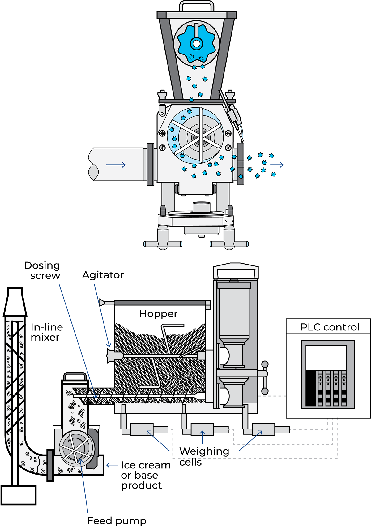
Fig 21.17 Working principle of the ingredient dosing and the feed pump (rotary lamella pump)
The feed pump is a rotary lamella pump, where three lamellas are mounted on a rotor. The product from the continuous freezer is pumped through the lamella pump by the freezer, and the ingredients from the hopper are supplied to the flow continuously.
The inline mixer ensures a homogeneous distribution of particles in the ice cream.
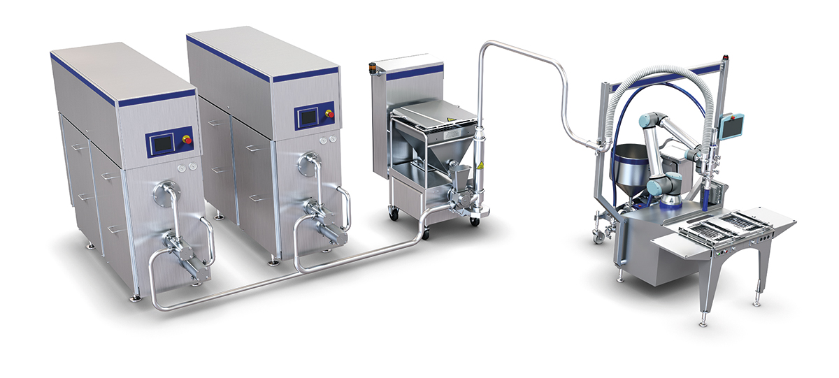
Fig 21.15 Placing the ingredient dosing unit on a line
Moulding process
Further processing of the ice cream can be done in several ways. The less complicated method is to fill either a liquid mix or semi-frozen product into a mould that is submerged into a cooled brine. If the mould is filled with semi-frozen product, the viscosity must be low enough to ensure that the product can flow down into the mould. The mould features a conical design to extract the products after hardening.
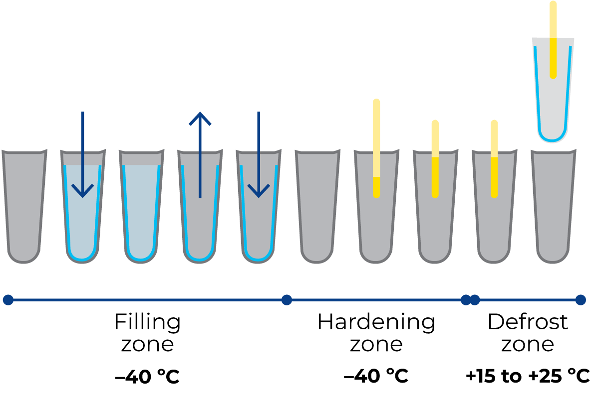
Fig. 21.18 Working principle for filling, for example, shell-in-core product
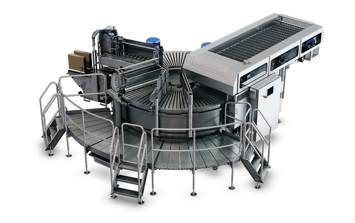
Fig. 21.19 Rotary moulder
Moulding is a diverse processing solution capable of producing a wide range of different products.
The mould is immersed in a brine (saline solution) cooled to between –40 °C and –38 °C, thereby cooling and freezing the product inside the mould.
The illustration shows an example of a shell-in-core product. The mould is first filled with a water-ice mix where the outer layer is frozen. The non-frozen water-ice mix is removed using a vacuum pump, and the mould is then filled with an ice cream mix. A stick is inserted when the product is partially frozen. After hardening, the product enters the defrost zone where 15 °C to 25 °C water is sprayed onto the moulds, generating a melting film that enables the extraction of the products.
The products can then be dipped in chocolate, dry-coat or something else, after which they are wrapped, packed in boxes and transferred directly to cold storage.
The moulding unit can be designed as a round moulding table, where the mould table rotates indexed.
The moulding unit can be designed as an inline process, where the working area is not limited to 360° as the rotary moulder, and thus more complex variants can be made. The functionality is identical to the rotary moulding unit.
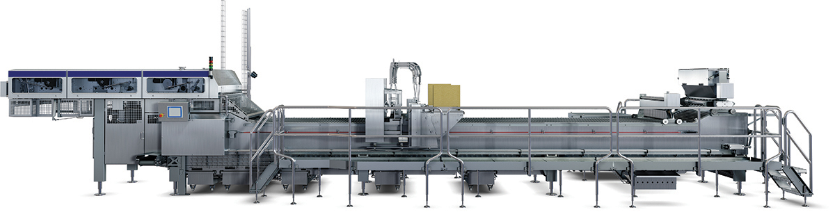
Fig. 21.20 Linear moulder
Filling process
After the continuous freezing process, the ice cream can be filled into a cup or container of various sizes, shapes and types. It can also be filled in wafers. Most flat-top wafers are made on a filling unit. A filling unit is characterised as an indexed operation.
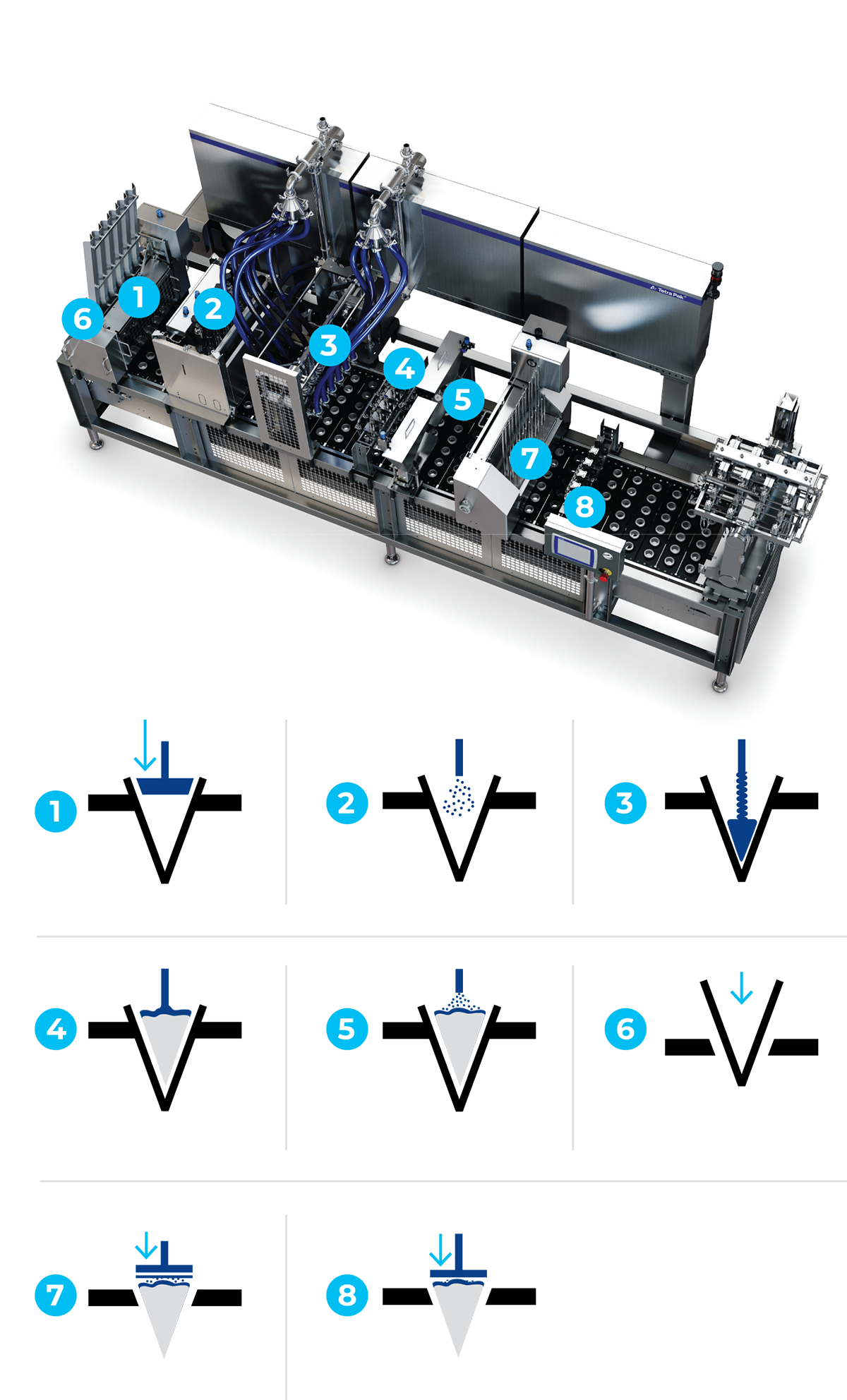
Fig. 21.21 Ice cream filler
The working process for making a flat-top cone:
- Inserting the wafer with a paper cover
- The wafer is pressed into place (ensure correct placement and round shape of paper cover)
- Applying chocolate coating on the inside of the wafer
- Filling with ice cream
- Liquid topping of the products
- Dry topping of the products
- Possible insertion of another component (e.g.chocolate piece)
- Placing the paper lid
- Closing the paper lid
- Removal and transfer of products for further hardening
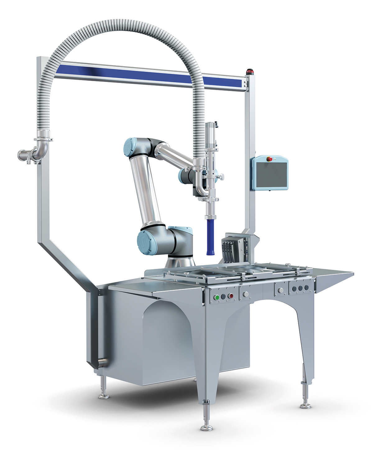
Fig. 21.23 Semi-automated unit with robotic filling arm
The process line requires that the products are fully hardened in a hardening tunnel before being transferred to storage.
It is possible to fill containers with a robotic filling unit. Collaborative robots have the advantage that they do not require safety guards – as they stop moving when touched – and can manually learn certain filling patterns. This makes it possible to fill containers with unique patterns.
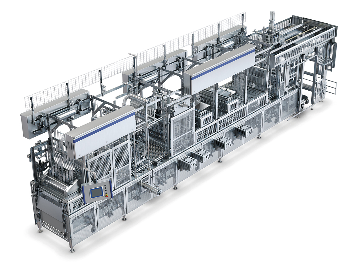
Fig. 21.22 Modular ice cream filler
Extrusion process
The most challenging shaping process for ice cream is extrusion. Not only are good operators required, but also an ice cream formulation that is adapted to the technology. Extrusion can be done as vertical or horizontal extrusion. Additionally, the products can be filled using time-elapsed extrusion via a time-controlled valve.
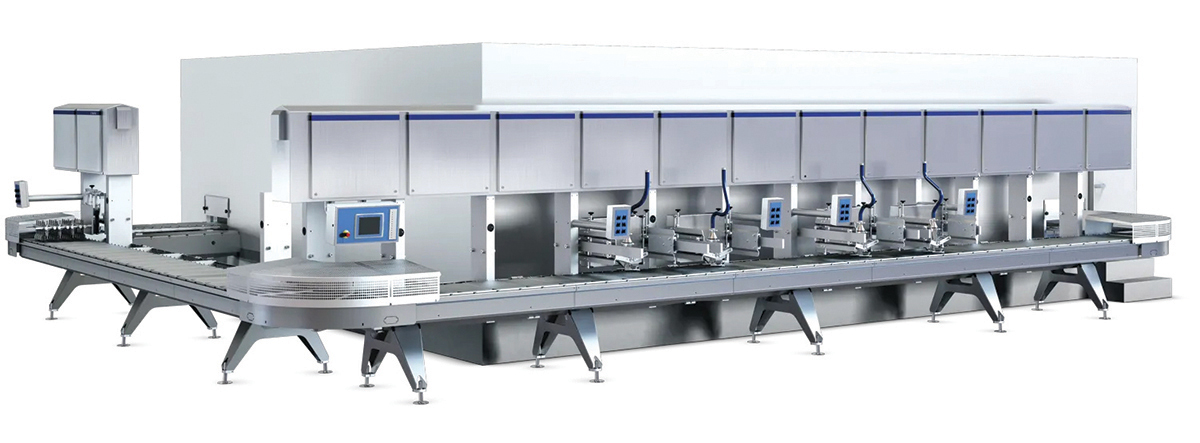
Fig. 21.24 Extrusion tunnel
In contrast to the indexed operation of the moulding and filling technologies, extrusion takes place using continuous flow. Since the back pressure is not built up in the filling line as a result of the discontinuous flow when using the open/close valve, the system can handle a higher viscosity. This means that the amount of water frozen in the continuous freezer can be increased, improving the texture and therefore the quality of the final ice cream.
Extrusion is characterised by the fact that it is possible to work with shapes and colour combinations and that the products are of high technical quality. The products include sticks, funny-faces, wafers, sandwiches, mini-products and bar products.
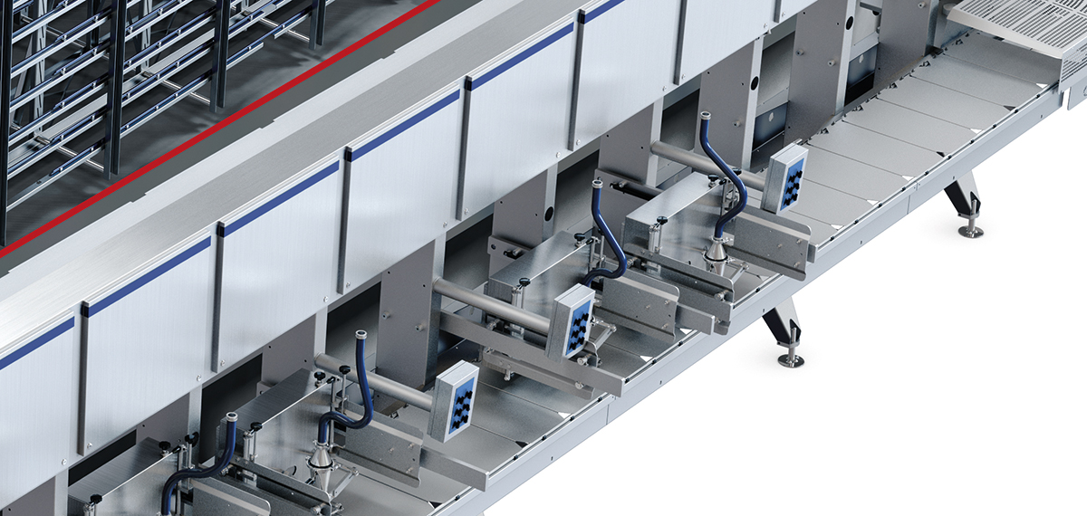
Fig. 21.25 Workstations on the workbench for an extrusion tunnel
The extrusion process takes place on equipment where the products are placed on trays that are conveyed continuously throughout the process, so all operation units are synchronised with the movement of the trays.
The products are placed on the trays on the workbench. On the workbench, there can be several other functions, such as placing the bottom and top biscuits for sandwiches, a waffle, liquid or dry topping on the products as well as other decorations. Depending on the capacity, up to four extrusion workstations can be placed across the trays.
The trays are transported by the chain from the workbench and into the hardening tunnel. The hardening tunnel can either be an insulated building or an isolated part of an existing building. In the hardening tunnel, evaporators are placed that lower the air temperature to –40 °C.
Inside the tunnel, the trays are pulled around on a stand that ensures the correct hardening time to achieve a complete hardening of the products, which takes about 18 – 25 minutes depending on the tunnel and speed. To increase freezing, fans are placed in the tunnel which maximises the hardening of the products using high air speeds.
The products are hardened when a minimum of 80% of the water is frozen into ice crystals, after which the trays with the products leave the tunnel.
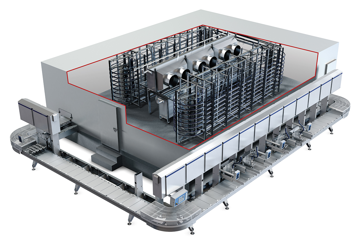
Fig. 21.26 Chain and blowers in a hardening tunnel for an extrusion tunnel
Since the products are frozen to the trays, there is a need to loosen them (product release). Here, a pneumatic tapping device releases the products, while the products are held in position. If the products lose position, there may be challenges in picking them up from the trays, which results in increased waste on the line.
The products are collected with a servo arm that picks up the products using a gripper.
The products are placed in a holder on a lamella, which transports and handles the products over any dipping stations.
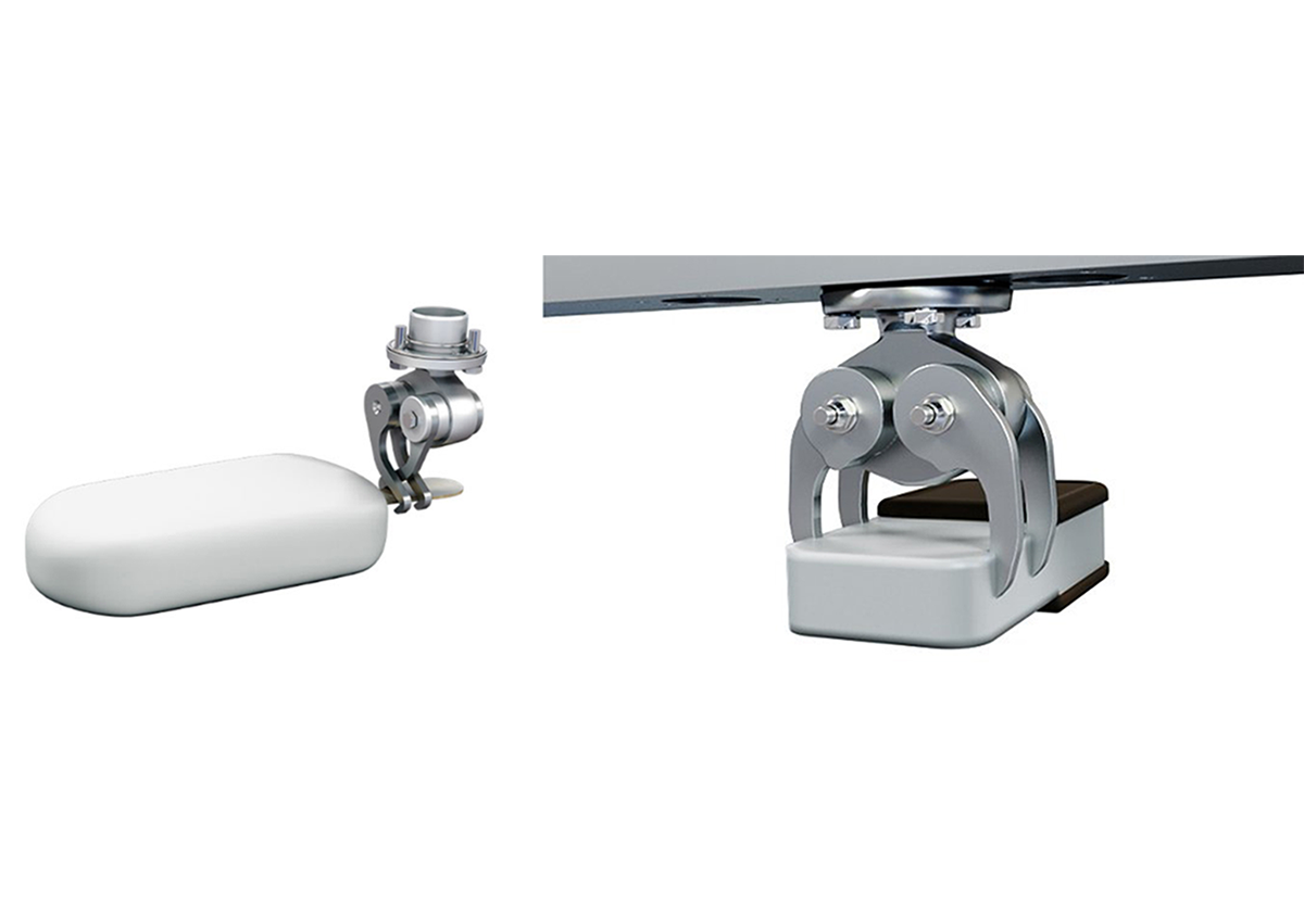
Fig. 21.27 Different grippers for collecting the products
Depending on the technology, the dipping tank is either lifted up to the products, or the lamellas are moved down so that the products are dipped into the dipping tank. The dipping can range from a common single chocolate dip to more advanced products that involve several layers of chocolate, caramel and/or fruit ripple. This requires that the products are dipped in liquid nitrogen between the different dips, whereby the inner layer and/or middle layer are frozen. Several dips in liquid nitrogen are also used when making a fruit juice coating.
After the products are coated, the products are transferred to the next unit operation, where the products are individually wrapped.
Wrapping process
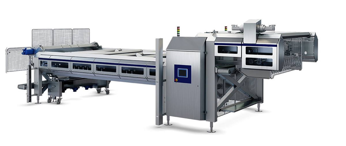
Fig. 21.28 Dip and transfer unit for collecting products from trays, placing in lamellas, dipping in coating trays and depositing for wrapping
The ice cream products can be individually wrapped in paper. This is done on the wrapping unit, where the products are placed in a continuous string of paper. The paper is assembled and sealed around the products (fin sealing) followed by sealing and cutting (cross-sealing) across the paper direction so that the products are individually packed.
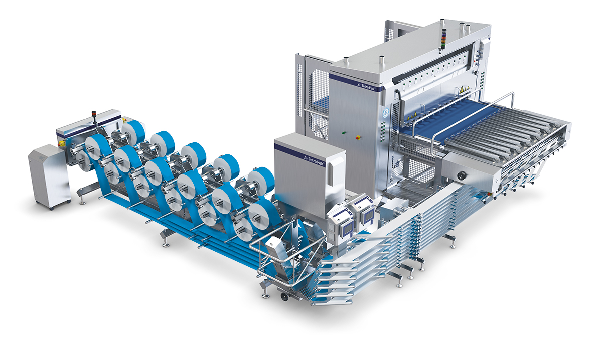
Fig. 21.29 Multilane wrapper
During the packing process, several sensors ensure that the cross-sealing is correctly positioned in relation to the paper print using a photomark on the paper
Fig. 21.30 Photomark to ensure correct placement of products and cross-sealing in relation to decoration on wrapping paper
Ice cream production plants
The illustrated plant layout illustrates the process unit placement and product flow in ice cream production.
- Mix preparation
- Ageing tanks
- Continuous freezers
- Bulk filling
- Cone filling
- Moulding
- Extrusion
- Cartoning
- Storage
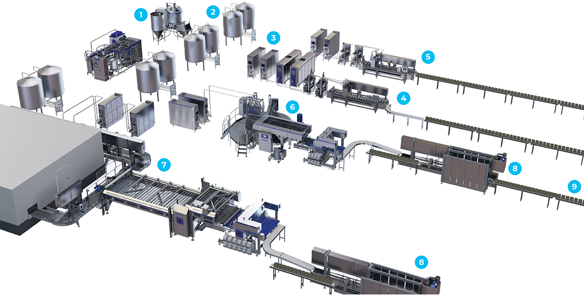
Fig. 21.31 Ice cream plant for production of 5,000 to 10,000 l/h of various types of ice cream