MILK AND WHEY FRACTIONATION
Whey processing
Whey is defined as the liquid residue of cheese, casein and yoghurt production, and it is one of the biggest reservoirs of food protein available today. Whey comprises 80 – 90% of the total volume of milk entering the process and contains about 50% of the nutrients in the original milk: soluble protein, lactose, vitamins and minerals.
Whey can also be obtained from milk by microfiltration and can be fractionated further by using ultrafiltration, harvesting whey proteins as valuable ingredients and creating whey permeate as a secondary product comprising mostly lactose, minerals and some acids. The latest research shows that whey protein is arguably the most nutritionally valuable protein available. It is little wonder that nutritional markets such as sports, clinical and infant nutrition are driving an unprecedented investment in dairy production. Packed full of “natural goodies” such as high-gelling β-lactoglobulin, mother’s milk equivalent protein a-lactalbumin, lactoferrin, and immunoglobulin and as a pre-cursor to the probiotic galacto-oligosaccharides (GOS), whey is proving to be one of the most exciting nutrient sources available today.
Whey as a by-product from the manufacture of hard, semi-hard or soft cheese and rennet casein is known as sweet whey and has a pH of 5.9 – 6.6. Whey as a by-product from the manufacture of fresh cheese types like cottage cheese is known as acid cheese whey and has a pH of ~5. The manufacture of mineral-acid precipitated casein yields acid whey with a pH of 4.3 – 4.6. Table 18.1 shows approximate composition figures for whey from cheese and casein manufacture.
Whey is very often diluted with water. The figures above relate to undiluted whey. As to the composition of the NPN fraction, about 30% consists of urea. The remainder consists of amino acids and peptides (glycomacropeptide from renneting action on casein). Table 18.2 lists some fields of application for whey and whey products.
Advances in membrane filtration and chromatography have underpinned economically viable commercial processes for the fractionation of whey into highly purified protein and lactose products that allow end users to take advantage of the various functional properties of individual whey components. This is a trend that is expected to continue as research uncovers new bioactive properties and consumers become more educated about the nutritional value of whey.
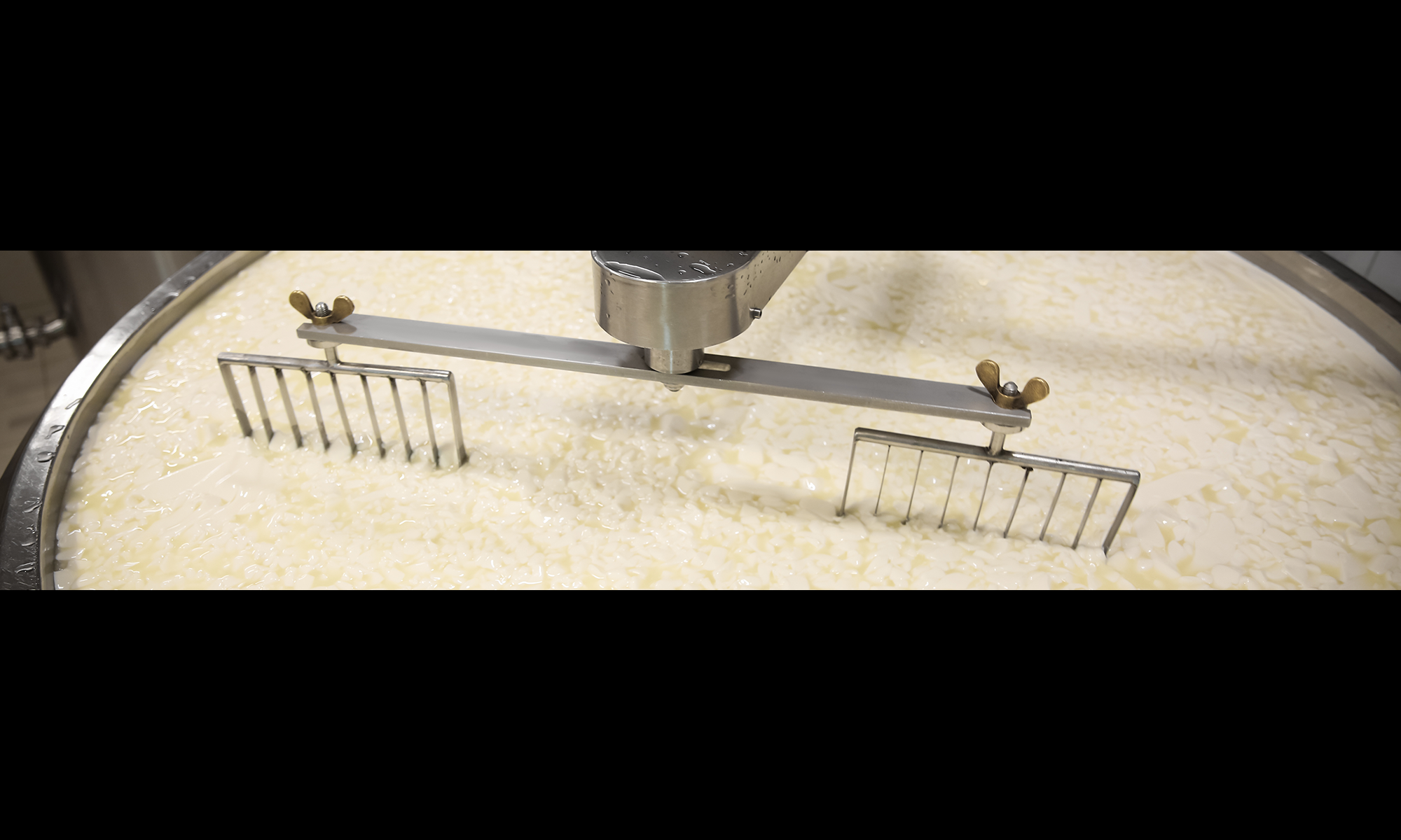
The block diagram in Figure 18.1 summarises various processes used in the treatment of whey and its end products. The first stage is filtering the curd particles left in the whey, followed by the separation of fat and casein fines (Figure 18.2), partly to increase the economic yield and partly because these constituents interfere with subsequent treatment.
Production of whey powder, delactosed whey, and lactose has traditionally dominated the processing of whey solids. However, the increased demand for whey proteins has resulted in approximately 50% of processed whey solids being directed to associated products WPC35-80, whey protein isolate (WPI), lactose and permeate. The shift in the image of whey from an unwanted by-product to a highly valuable nutritional source is complete. Some of the products now in use are described in this chapter.
Abbreviations and definitions for the above table
Dem. Demineralised, minerals that are removed from the whey
Delac. Delactosed, whey that has been depleted of lactose
Deprot Deproteinised, some of the proteins have been removed from the whey
TOP/TS Total protein content in dry matter/ total solids
WPC Whey protein concentrate (ranging from 20 – 85% TOP/TS)
WPI Whey protein isolate, fat-depleted WPC with > 90% TOP/TS
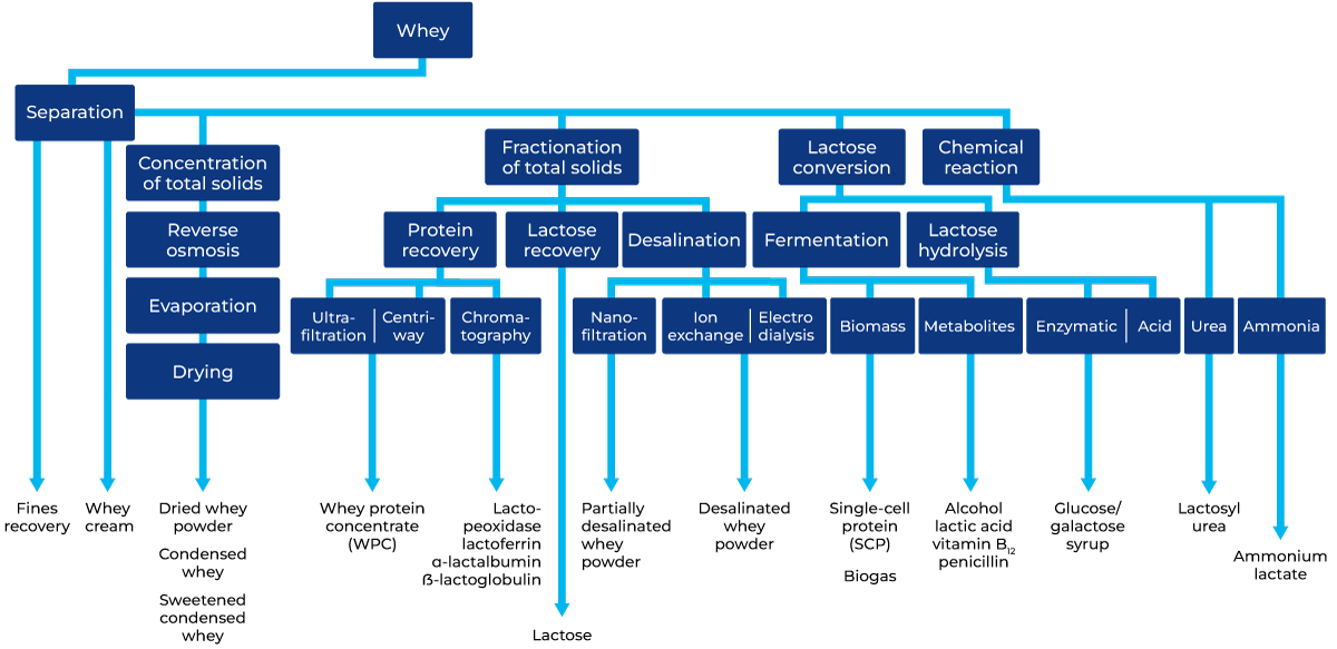
Fig. 18.1 Whey processing alternatives.
Different milk and whey process steps
Whey, akin to milk, needs immediate processing upon reception or when separated from cheese curd, as its temperature and composition facilitate bacterial growth, resulting in protein breakdown and lactic acid formation.
It is recommended that milk and whey be cooled, and from reception and storage follow similar steps – clarification, fat separation, pasteurization and cooling to await further processing.
Milk and whey pre-treatment
Milk and whey fat are recovered in centrifugal separators
The centrifugal separation processes like clarification (in which the solid impurities are separated), bactofugation (using a centrifugal separator for removing spores and some of the bacteria) and fat separation are mostly done warm at ~40 – 50 °C and in line with a regenerative heat exchanger and pasteurization step.
In milk processing, a fat separator is typically incorporated into the process. In cheese production, cheese milk often involves the use of a fat separator and, optionally, bactofugation. Conversely, deriving whey from cheese generally involves a course filter, a fines clarifier, a fat separator and often a reverse osmosis module (see figure 18.3).
Where milk cream typically has a fat content of 40%, whey cream often has a fat content of 25 – 30%, which can partly be reused in cheese-making to standardize the cheese milk. In that case, the whey cream needs to be sterilised to inactivate enzymes, bacteria and bacteriophages. This enables the corresponding quantity of fresh cream to be utilised for special cream products. Normally, this works well for short maturation cheeses such as mozzarella, but note that the risk of rancid off flavours is heightened as the maturation time increases. It is important to break the recycle loop to avoid the build-up of free fatty acids and other undesirables that are not trapped in the curd matrix. Cheesemakers may prefer not to re-use the whey cream due to, e.g. sensitivity of the starter to bacteriophages. In some of these cases, whey cream may be converted to whey butter.
Whey casein fines recovery and fat separation

Fig. 18.2 Example of whey processing at a cheese production plant.
Casein fines in the form of curd grains of curd fines are always present in whey. They have an adverse effect on fat separation and should therefore be removed first. Various types of separation devices can be utilised, such as course filters or centrifugal separators (Figure 18.2).
The collected fines are often pressed in the same way as cheese, after which they can be used in processed cheese manufacture.
If a cheese dairy is re-using the whey cream for cheese milk standardization, an alternative application is also possible by homogenizing the collected casein residue and re-introducing it with the whey cream (via a sterilisation step) to the cheese milk standardization. This enables the corresponding quantity of casein in milk to be utilised for other dairy product applications or to increase cheese production. Note that depending on the country and processing method, application may still be restricted due to granted patents.
Especially in fresh cheese and low-fat semi-hard cheese production, it may be beneficial to ultrafilter a part of the defatted whey to obtain whey concentrate. The whey proteins are then microparticulated using heat-based denaturation and mechanical shear-based protein-aggregate sizing. The microparticulated whey proteins are re-introduced at cheese milk standardization to improve cheese properties, e.g. moisture content. The heating intensity at microparticulation needs to be sufficient to also inactivate enzymes, bacteria and bacteriophages.
Pasteurization and chilling
Milk and whey that is to be stored before further processing must be either chilled or pasteurized and chilled as soon as the fat and fines have been removed.
It is common practice to recover the thermal energy from the whey by warming up water. That warm water is used to pre-heat the cheese milk in the pasteurizer or milk heater. Thus, the water exchanges thermal energy recovered from the whey to the cheese milk. As both processes – milk heating and whey cooling – are not always present simultaneously, the water is collected in-between processes in a heat recovery silo. In this silo, warm water (from the whey cooler) floats over cold water (from the milk heater) so the silo can act as a temporary storage of thermal energy from the whey when (for a time) energy cannot be exchanged to the milk.
For short-time storage (< 8 hours), chilling to < 5 °C is usually sufficient to reduce bacterial activity. In high-quality infant formula and sports nutrition applications, incorporating milk and whey necessitates pasteurization directly after removing fat and fines. This approach is generally recommended to meet the rising standards for product quality.
Fig. 18.3 Fines and fat separation from whey.
1. Course filter
2. Whey collecting tank
3. Clarifier
4. Whey cream separator
5. Whey pasteurizer
6. Reverse osmosis module
Concentration of total solids
Concentration
The initial stage of concentrating milk and whey typically entails elevating the dry matter content from approximately 9% to 14 – 30% for milk, achieved through reverse osmosis (RO), and from around 6% to 18 – 28.5% for whey, accomplished using either RO alone or a combination of RO and nanofiltration (NF). Subsequently, the whey can be transported to another location for additional processing such as evaporation and drying, or it can be evaporated and dried directly on-site.
In practical applications, when the dry matter content exceeds 30%, mechanical vapour recompression (MVR) evaporation is commonly employed to further concentrate milk and whey. Employing MVR in this subsequent phase of milk concentration can elevate the dry matter to 48 – 51% total solids (TS), while for whey concentration, it can raise the dry matter from as little as 20% to 45 – 65%.
Following evaporation, the concentrated milk can be fed directly into the spray dryer, whereas whey is typically rapidly flash-cooled to 30 – 40 °C to initiate lactose crystal nucleation. It is then stirred in specially designed crystallisation tanks while undergoing further cooling. The whey concentrate remains in the crystallisers for 4 – 8 hours to achieve a specific degree of lactose crystallisation, resulting in a reduced-hygroscopic product upon spray drying.
For more information on RO and Evaporators, see Chapters 7.4 and 7.6.
Drying
Milk and whey are dried in similar ways, i.e. in drum or spray dryers, see Chapter 19, Milk and whey powdered ingredients.
The use of drum dryers involves a problem: milk powder’s functional and instant properties are deteriorated by drum drying. For whey powder, it is difficult to scrape the layer of dried whey from the drum surface. A filler, such as wheat or rye bran, is therefore mixed into the whey before drying, to make the dried product easier to scrape off.
Spray drying of milk and whey, is at present, the most widely used method of drying. Milk powder products are usually protein-standardized by adding lactose or milk permeate prior to evaporation and drying. Before being dried, the whey concentrate is usually evaporated, flash cooled and crystallised to form small lactose crystals, as this results in a reduced-hygroscopic product which does not go lumpy when it absorbs moisture.
Acid whey from cottage cheese and casein production is difficult to dry due to its high lactic acid content. It forms lumps in the spray dryer. Drying can be facilitated by neutralisation and additives, such as skim milk and cereal products.
Fractionation of total solids
Protein fractionation and concentration
Milk and whey proteins were originally isolated using various precipitation techniques, such as heat coagulation and acid precipitation or a combination of both. Nowadays, membrane separation (fractionation) and chromatographic processes are used in addition to both precipitation and complexing techniques.
Fink and Kessler (1988) state that a maximum whey protein denaturation rate of 90% is possible for all denaturable fractions. Proteose peptone, comprising some 10% of the fraction, is considered un-denaturable.
Proteins from milk and whey can be isolated through chromatography and membrane separation, followed by careful spray drying. Whey proteins obtained through membrane separation or ion exchange exhibit favourable functional properties such as solubility, foaming, emulsion formation, and gelling.
Protein concentration by UF
The protein content of skim milk is approximately 35% in dry matter, while whey contains approximately 13% protein in dry matter. Whey protein concentrate powders (WPC) are derived from drying the retentates obtained through ultrafiltration of whey. Their protein content, ranging from 35% to 80%, is represented as a percentage of the dry matter. To achieve a protein content comparable to skim milk, liquid whey undergoes ultrafiltration to concentrate it to approximately 9% dry matter, containing 35% whey protein. Whey protein concentrates exhibit an excellent amino acid profile, with notable proportions of available lysine and cysteine.
Example: 100 kg of whey yields approximately 17 kg of retentate and 83 kg of permeate at close to six-fold (5.88) concentration. Table 18.3 shows the compositions of the feed (whey) and the resulting WPC35 retentate and permeate.
A process line to produce dried whey protein concentrate using UF is shown in Figure 18.4. Up to 95% of the whey is collected as permeate and protein concentrations as high as 80 – 85% (calculated based on the dry matter content) can be obtained in the dried product.
Percentage of protein in dry matter according to the values in Table 18.3:
In concentration, most of the true protein, typically > 99%, is retained, together with almost 100% of the fat. The concentrations of lactose, NPN and ash are generally the same in the retentate serum and permeate as in the original whey, but a slight retention of these components is reported.
The overall retention figures, as described in Chapter 7.4, Membrane technology, depend on:
- The type of membrane
- The flux
- The character of the feed
To achieve a protein concentrate exceeding 80%, the liquid milk and whey undergo ultrafiltration to reach a solids content of 12 – 18% for MPC85, MCC85 (milk protein/micellar casein concentrates) and 27 – 32% for WPC80 (whey protein concentrates).
Typically, for WPC35, as with milk and MPCs, an evaporator is used to concentrate before spray drying. For WPC with protein concentration above 60% dry matter, to minimise heat damage instead of evaporation, a nanofiltration step is used to feed > 35% dry matter prior to spray drying.
Table 18.4 shows the compositions of some typical milk protein concentrate (MPC) and micellar casein concentrate (MCC) powders and milk WPI.
Fig. 18.4 Process for recovery of a dried protein concentrate using UF.
1. UF unit
2. Buffer tank for UF permeate
3. Buffer tank for whey retentate
4. Evaporator
5. Spray dryer
6. Bagging
Protein fractionation and concentration by MF

Fig. 18.5 Process for native whey, WPI & (milk) UF-permeate from skim milk.
1 Microfiltration plant
2 Microfiltration retentate collection tank
3 Ultrafiltration-Diafiltration plant
4 Permeate reverse osmosis - nanofiltration plant
5 Concentrated permeate collection tank
6 Whey protein isolate & MCC collection tank
7 Ultrafiltration plant
8 WPI & MCC high concentration mem-brane plant
9 Reverse osmosis/ polishing plant
10 Water storage tank
11 WPI & MCC preheater
12 Spray dryer
13 Bagging
The use of whey protein isolate (WPI) containing > 92% protein in dry matter is growing rapidly in applications such as body-building supplements, where the fat and other non-protein constituents are undesirable, as well as in egg white replacements for whipped products such as meringues or as a valuable ingredient in foods and acidic fruit beverages.
Advances in microfiltration have drastically improved the quality and economics of available products, moving from a traditionally hot ceramic filter process to a “cold” organic spiral-wound process in recent years.
Milk whey protein isolate (WPI) derived directly from skim milk is produced through the microfiltration of skim milk, yielding a retentate known as milk colloidal casein concentrate (MCC) and a microfiltration (MF) permeate referred to as “ideal” or “native” whey. The UF concentration of this microfiltration permeate results in milk WPI, which is attracting increasing interest due to its unique properties arising from the absence of traditional cheese-making processes involving rennet, starter cultures, or acid. Consequently, milk WPI lacks glycol-macro peptide (GMP), maintains lactic acid levels consistent with natural occurrence, prevents protein degradation by starter culture enzymes, and mitigates risks associated with bacteriophages.
As depicted in Figure 18.5, the initial step involves microfiltration (1) of skim milk to separate casein (yielding MF retentate) from the MF permeate (referred to as ideal whey or native whey), which contains whey proteins, lactose, non-protein nitrogen (NPN), and ash. Ultrafiltration-diafiltration (3) is then utilised to separate the whey proteins (UF retentate) from lactose, ash and NPN (UF permeate) giving a protein-rich stream with > 90% protein in dry matter. After storage (6), the UF retentate can be further concentrated to 36 – 37% dry matter (8), preheated (11) to attain specific functional properties and dried (12) to no greater than 4% moisture.
The resulting MF retentate (2), containing the casein fraction can be further processed to MCC (micellar casein concentrate) via ultra filtration (7). When used in liquid form, it is added to various products benefiting from casein fortification, for example cheese. Alternatively, after high concentration (8) and heating (11) it can be dried (12) to be available as MCC powder. Sometimes the UF plant (7) is located before the MF plant, making it a skim milk UF for MPC’s and reducing the size of the MF plant.. Examples of milk WPI and MCC powder compositions are provided in Table 18.4.
As depicted in Figure 18.6, defatting of whey protein concentrate from cheese whey for making WPI containing > 90% protein dry matter also requires a microfiltration step. The MF retentate will yield high-fat WPC. Typically, whey UF retentate at around 35% protein in DM feeding the MF will result in a fat content reduction from over 7% to less than 0.4%. Microfiltration also concentrates fat globule membranes and most of the bacteria in the MF retentate, which is collected and processed separately; in some cases, this retentate is dried on the same dryer as the WPI, resulting in a high-fat WPC70 powder. The defatted MF permeate is routed to a second UF plant for concentration to make WPI; this stage also includes diafiltration.
As Figure 18.6 shows, the pre-treated whey (1, 2 and 3) is pumped to a UF plant (5) where it is concentrated to about 35% protein in DM. The retentate is pumped to the MF plant (6), while the permeate goes to a collecting tank after.
RO concentration and cooling
The retentate from MF treatment, which contains most of the fat and bacteria, is collected separately, and the defatted permeate is forwarded to further ultrafiltration with diafiltration (7). The resulting WPI retentate is then further concentrated using (8) NF (35 – 37% DM) and spray-dried to reduce the moisture content to a maximum of 4% before bagging.
Recovery of denatured whey protein
In general, serum protein or whey proteins cannot be precipitated by rennet or acid. It is, however, possible to precipitate whey proteins with acid, if they are first denatured by heat. The process is divided into two stages:
- Precipitation (denaturing) of the protein by a combination of heat treatment and pH adjustment
- Concentration of proteins by centrifugal separation
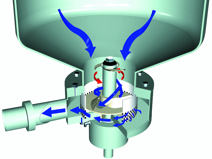
Fig. 18.6 Process for defatting of whey protein retentate.
1 Pasteurizer
2 Clarifier
3 Separator
4 Holding tank
5 First UF plant
6 MF for fat removal
7 UF and diafiltration
8 Nanofiltration
Denatured whey proteins can be mixed with cheese milk prior to renneting; they are then retained in the lattice structure formed by the casein molecules during coagulation. This discovery led to intensive efforts to find a method of precipitating and separating whey proteins, as well as a technique for optimising the yield. Adding denatured whey proteins to the cheese is not permitted by law in several countries, and also for certain types of cheese. Denatured proteins, either by adding or by pasteurization at high temperatures, affect both the yield and ripening of the cheese. Figure 18.7 shows the Centri-Whey process line for the manufacture of denatured whey proteins. After pH adjustment, the whey is pumped via an intermediate tank (1) to a plate heat exchanger (2) for regenerative heating. The temperature of the whey is raised to 90 – 95 °C by direct steam injection (3), before it passes through a tubular holding section (4) with a holding time of 3 – 4 minutes. Acid is introduced during this stage, to lower the pH. Those proteins that can be, and have been, modified by heat are precipitated within 60 seconds in a tubular holding section (4).
After regenerative cooling to about 40 °C, the precipitated proteins are separated from the liquid phase in a solids-ejecting clarifier (6). The clarifier discharges, at roughly 3-minute intervals, the accumulated protein in the form of a 12 – 15% concentrate, of which about 8 – 10% is protein. This method results in 90 – 95% recovery of the coagulable proteins. Microparticulation as indicated in fig. 18.2 is another way of doing this.
The addition of concentrated whey protein to cheese milk – principally in the manufacture of soft and semi-hard cheeses – causes only minor changes in the coagulating properties. The structure of the curd becomes finer and more uniform than with conventional methods. The processed whey proteins are more hydrophilic than casein. In the making of Camembert cheese, for example, an increase in yield of 12% has been reported.
Chromatographic protein isolation, and further purification
Milk serum proteins or whey proteins can be separated and purified into components such as a-lactalbumin, β-lactoglobulin, and lactoferrin. The process involves altering the pH, salt concentration, and temperature to take advantage of the proteins’ solubility and electrical charge.
As an example, for which the process will be more elaborately explained in Figure 18.16 and section “Demineralisation ion exchange chromatography”, lactoferrin can be extracted from milk or whey. For the highest yield, it is extracted from unpasteurized skim milk, binding undenatured lactoferrin molecules to chromatography columns. In this process, milk containing lactoferrin is passed through the column to collect protein. Lactoferrin molecules bind to an ion-exchange resin within the column or stationary phase, resulting in lactoferrin-depleted skim milk exiting the columns.
The isolated lactoferrin is collected by washing the ion-exchange resin in the columns with a brine solution. The collected solution (eluate) undergoes additional filtering steps (ultrafiltration) to eliminate impurities and concentrate the protein. Finally, lactoferrin is dried into a powder form.
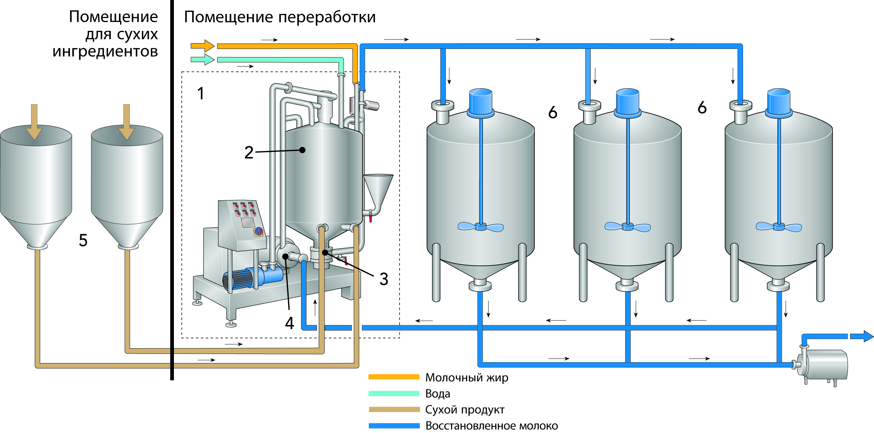
Fig. 18.7 Recovery of denatured whey proteins.
1. Whey collecting tank
2. Plate heat exchanger
3. Steam injector
4. Holding tube
5. Acid tank
6. Clarifier
7. Collecting tank for denatured whey protein
UF permeate, lactose fraction and concentration
Milk and whey UF permeate
UF permeate from the production of MPC, WPC and WPI can be spray-dried or used for lactose production as shown below.
There are currently a few options available for the further processing of UF permeate from whey or skim milk as shown below. Only milk UF permeate, and lactose can be used for the standardization of protein in milk powders.
The processes for the manufacture of lactose and permeate powder are explained in Figure 18.8 and Chapter 19, Milk and whey powdered ingredients.
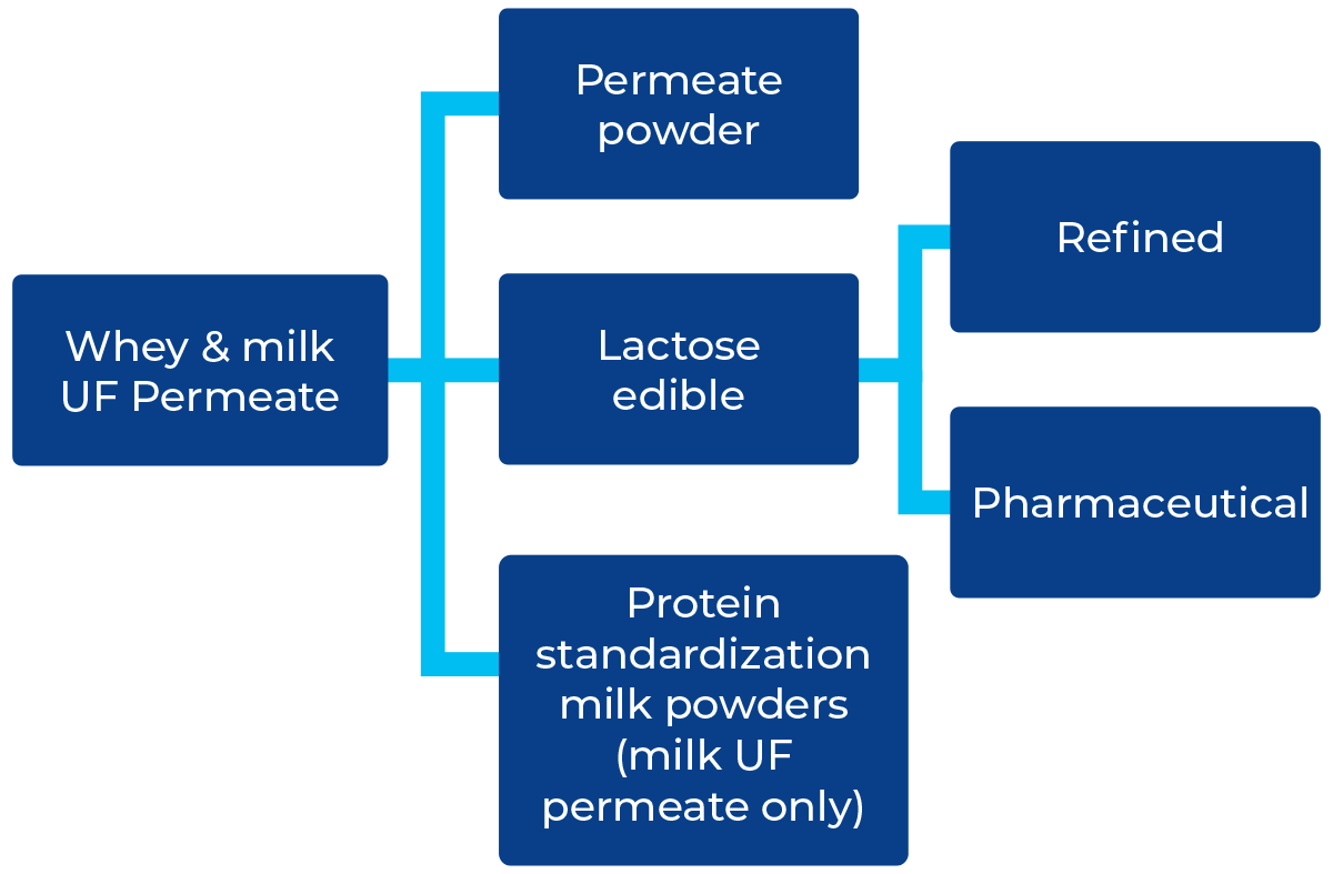
Fig. 18.8 Some typical options for the utilisation of milk and whey UF permeate.
Lactose recovery
Skim milk solids comprise > 50% lactose, and in whey dry matter > 70%, so lactose is a major constituent. For whey (not for milk) there are two basic methods of recovery, depending on the raw material:
- Crystallisation of the lactose in untreated but concentrated whey
- Crystallisation of lactose in whey from which the protein has been removed by UF, or some other method, before concentration
Both methods produce a mother lye, molasses, which can be dried and used as fodder. The feed value can be increased considerably if the molasses is desalinated and if high-quality proteins are added.
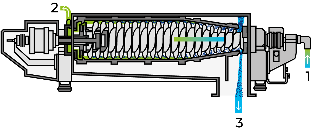
Fig. 18.9 Decanter centrifuge.
1. Feed
2. Outlet for liquid phase
3. Outlet for solids phase
Crystallisation
The crystallisation cycle is determined by the following factors:
- Crystal surface available for growth
- Purity of the solution
- Degree of saturation
- Temperature
- Viscosity
- Agitation of the crystals in the solution
Several of these factors are related, such as the degrees of saturation and viscosity. Figure 18.10 shows a production line for the manufacture of lactose. The whey/UF permeate is first concentrated by evaporation to 60 – 62% DM and then transferred to crystallisation tanks (2), where seed crystals are added. Alternatively, demineralised, decalcified nano-filtered UF-permeate can be used and evaporated to 65% TS, feeding crystallisation tanks where crystallisation happens slowly, according to a predetermined time/ temperature program. The tanks have cooling jackets and equipment for control of the cooling temperature. They are also fitted with special agitators. After crystallisation, the slurry proceeds to decanter centrifuges and a sieve centrifuge for (3) the separation of the crystals, which are dried (4) to a powder. Following grinding (typically in a hammer mill) and sifting, the lactose is packed (5). For efficient and simple separation of lactose crystals from the mother liquor, crystallisation must be arranged so that the crystals exceed 0.2 mm in size – the larger the better for separation.
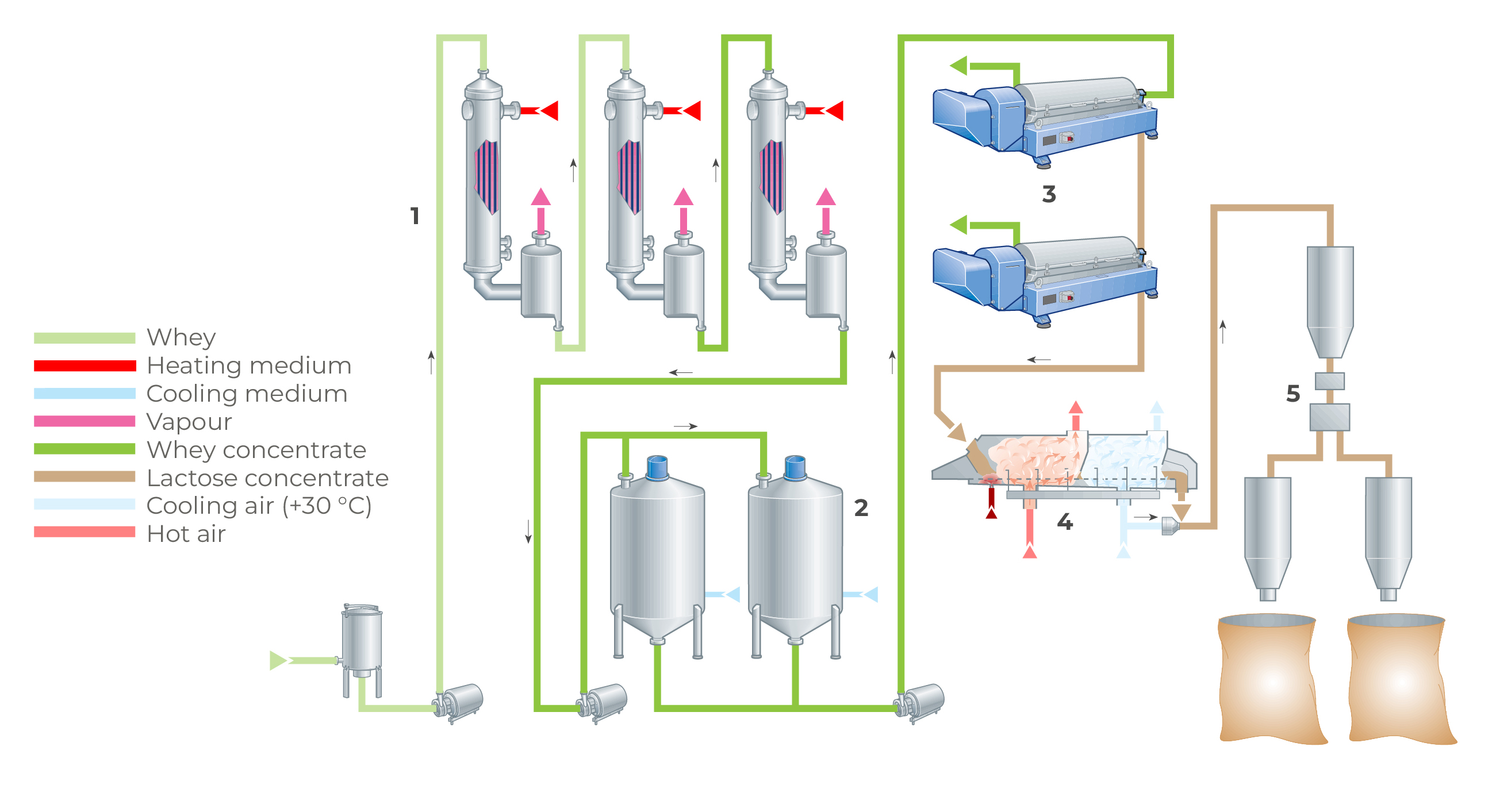
Fig. 18.10 Process line for lactose manufacture.
1. Evaporator
2. Crystallisation tanks
3. Decanter centrifuges
4. Fluid-bed dryer
5. Packing
The degree of crystallisation is determined in principle by the quantity of β-lactose converted to the desired a-lactose form, and the cooling of the concentrate must therefore be carefully controlled and optimised.
Lactose separation
Various types of centrifuges can be used for harvesting lactose crystals. One is the horizontal decanter centrifuge (Figure 18.9), which operates continuously and has a screw conveyor for unloading the lactose. Two machines are installed in series. The lactose from the first is reprocessed in the second for more efficient separation. During separation, impurities are washed from the lactose so that a high degree of purity is obtained. The residual moisture content of the lactose after the second separation stage is < 9% and pure lactose accounts for about 99% of the dry solids.
Drying
The lactose is dried after separation to a residual “free” moisture content of 0.1 – 0.3%, depending on the future use of the product. The temperature during drying should not exceed 93 °C, as β-lactose is formed at higher temperatures. The drying time must also be taken into consideration. During quick drying, a thin layer of amorphous (shapeless, non-crystalline) lactose tends to form on the a-hydrate crystal, which may later result in the formation of lumps. Drying usually takes place in a fluidised bed drier. The temperature is maintained at 92 °C and the drying time is 15 – 20 minutes. The dried lactose is transported through an air stream at a temperature of 30 °C, which simultaneously cools. The crystals are normally ground to a powder immediately after drying and are then packed.
Refining of lactose
A higher degree of purity or very white lactose is required for some applications (e.g. pharmaceutical manufacturing processes). The refining of lactose can also improve the yield of a lactose process. The traditional method for manufacturing pharmaceutical lactose involves redissolving lactose from the decanters at 60% DM in softened water at pH 4 and close to 100 °C, followed by mixing with active carbon and filter adjuvant. After filtration, the solution is recrystallised and centrifuged before drying, milling and packing. This is an expensive process where double execution of equipment is required for continuous processing, and where active carbon and filter adjuvant are sent directly to waste.
Alternative processes utilising continuous decalcification and riboflavin removal (which causes the yellow colour in lactose) with regenerable activated carbon columns produce refined white lactose much more economically. These methods can yield pharmaceutical-grade lactose with the inclusion of additional decanting and washing steps.
Permeate powder
An alternative to lactose from UF permeate is to convert the permeate into powder as described in the section “Concentration of total solids”, for which an example is shown in Figure 18.11, and in Chapter 19, Milk and whey powdered ingredients. The permeate powder has seen growth in animal feed and food applications when high-purity lactose is not required and ash content in the permeate is acceptable. Typically, this is a less capital-intense option, does not have the issues that can be associated with the disposing of the mother liquor, and has an almost 100% yield of the lactose.
Milk and whey UF permeates can be similar to cheese and native whey (as described in the section “Total concentration of solids” at the start of this chapter) concentrated by RO-NF (1) to 20 – 25% dry matter before it is evaporated using a single MVR evaporator and flash cooled (2) to initiate the spontaneous nucleation of lactose into small crystals and stored under controlled temperature conditions in specially-designed crystallisation systems (3) to cause a high degree of lactose crystallisation (> 75%). After around 4 – 6h, the crystallised permeate is fed to the spray-dryer installation. (4) Some dryers are designed to promote post-crystallisation of remaining lactose (> 95%) ensuring a free-flowing, non-hygroscopic product. The product is then stored (5) for up to 6h and then packed in 25 kg bags or powder tanker.
Alternative processes that bring about a very high concentration of permeate > 80% DM and continuous crystallisation prior to drying are also in use. High temperatures required to facilitate the handling of the highly viscous permeate concentrates should be chosen carefully because they can degrade product quality, particularly colour and flavour.
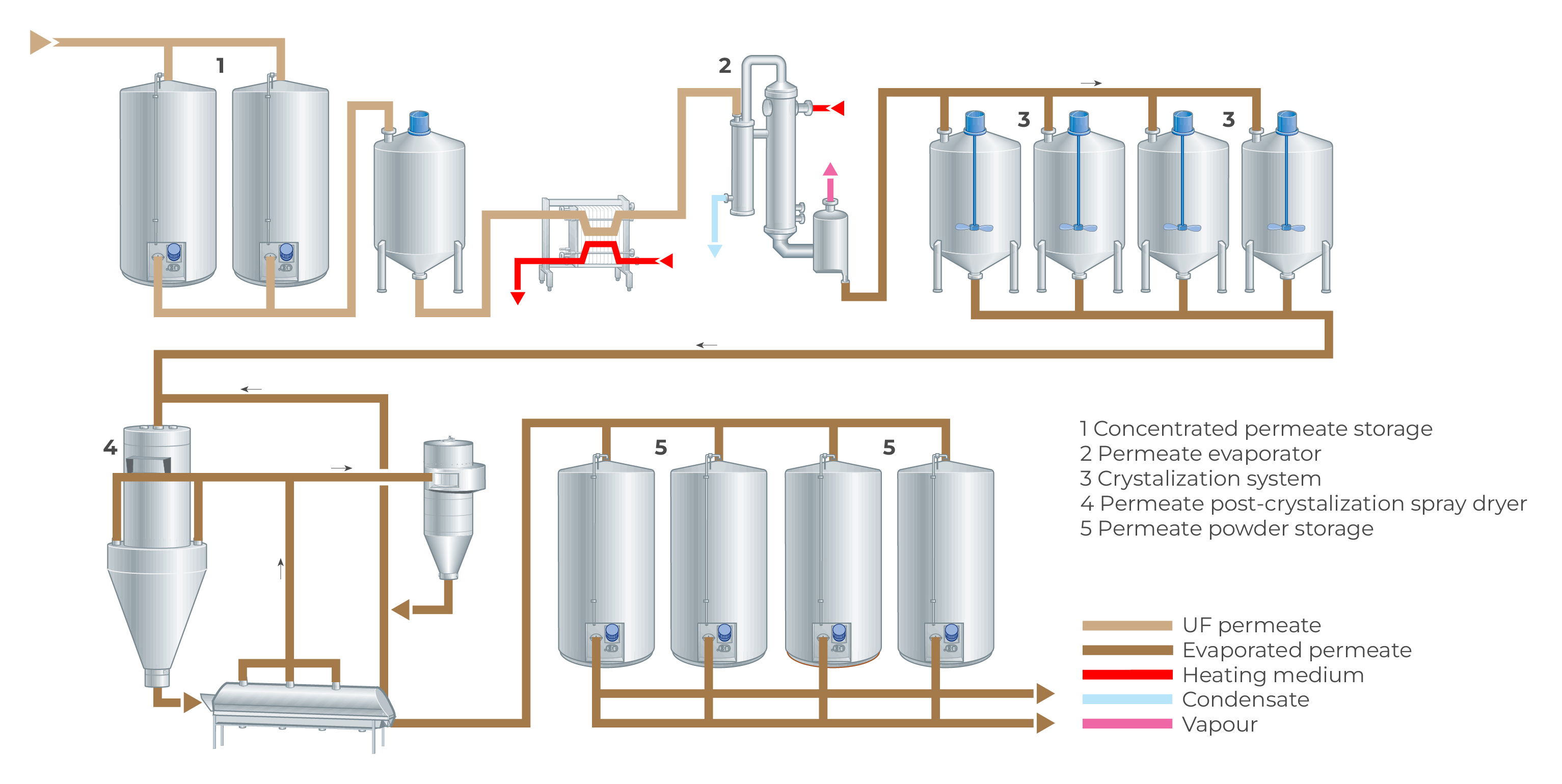
Fig. 18.11 Permeate process.
1. Concentrated permeate storage
2. Permeate evaporator
3. Crystalization system
4. Permeate post-crystalization spray dryer
5. Permeate powder storage
Demineralisation of whey and UF permeates
As native whey and especially cheese whey and UF permeates have fairly high salt contents, about 8 – 12% calculated on dry matter, their usefulness as ingredients in human foods is limited. By having it demineralised, various fields of application can be found in food and infant food partially (25 – 30%) or highly (90 – 95%) demineralised.
Partially demineralised whey concentrate can, for instance, be used in the manufacture of ice cream and bakery products or even in quark, whereas highly demineralised whey concentrate or powder can be utilised in infant formula and a very wide group of other products.
Principles of demineralisation
Demineralisation involves the removal of inorganic salts, together with some reduction in the content of organic ions, such as lactates and citrates.
The partial demineralisation is mainly based on the utilisation of crossflow membranes specially designed to “leak” particle species that have radii in the nanometre (10 – 9 m) range. This type of filtration is called nanofiltration (NF).
The high degree of desalination is based on either of two techniques:
- Electrodialysis
- Ion exchange
Partial demineralisation by NF
By using a specially designed “leaky” RO membrane, small particles like certain monovalent ions, e.g. sodium, potassium, chloride and small organic molecules (like urea and lactic acid) can escape through the membrane, together with the aqueous permeate. This membrane process is known by various names such as ultra osmosis, “leaky” RO and nanofiltration (NF).
Because of their greater compactness, spiral-wound membranes are most often used in new installations. For further information about this type of membrane, see Chapter 7.4 (Membrane technology) and Chapter 2, Figure 2.12 and Figure 2.13 Osmosis and reverse osmosis.
Examples of permeation rates of normal sweet whey constituents during nanofiltration are given in Table 18.6.
Remark: * Depending on the selected NF membrane and the supplier, the reduction of lactic acid and citric acid can be ~30%
As the table shows, the reduction of the chloride content in sweet whey can be as high as 70% and that of sodium and potassium 30 – 35%. The reason for this difference in the elimination of ions is the need to maintain an electrochemical balance between negative and positive ions.
A critical aspect of nanofiltration in whey processing is that the leakage of lactose must be kept to a minimum (< 0.1%), to avoid problems with high BOD (biological oxygen demand) in the wastewater (permeate). Installation of NF equipment in whey processing can be considered in the following situations:
- As a low-cost alternative to diminish the salty taste of ordinary sweet whey and UF permeate powder
- As a preliminary step towards a more extensive demineralisation of whey and UF permeate by electrodialysis and ion exchange
- For acid removal in hydrochloric and lactic acid casein whey and UF permeates; note that the permeation rate is low for lactate ions but high for free lactic acid molecules (see Table 18.6)
- For salt reduction in salted whey (e.g. salt drippings in cheddar cheese production)
High degree demineralisation
Electrodialysis
Electrodialysis is defined as the transport of ions through non-selective semi-permeable membranes under the driving force of a direct current (DC) and an applied potential. The membranes used have both anion and cation exchange functions, making the electrodialysis process capable of reducing the mineral content of a process liquid, e.g. salt water or whey and UF permeate.
The two electrodes at each end of the cell stack have separate rinse channels as shown in Figure 18.12, through which a separate acidified stream is circulated, to protect the electrodes from chemical attack.
For whey treatment, the whey feed and acidified brine pass through alternate cells in the stack, whose construction can be likened to that of a plate heat exchanger or plate sheet ultrafiltration module. Figure 18.12 is a schematic picture of an electrodialysis unit. It consists of several compartments separated by alternate cation and anion exchange membranes which are spaced about 1 mm or less apart. The end compartments contain electrodes. There can be as many as 200 cell pairs between each pair of electrodes.
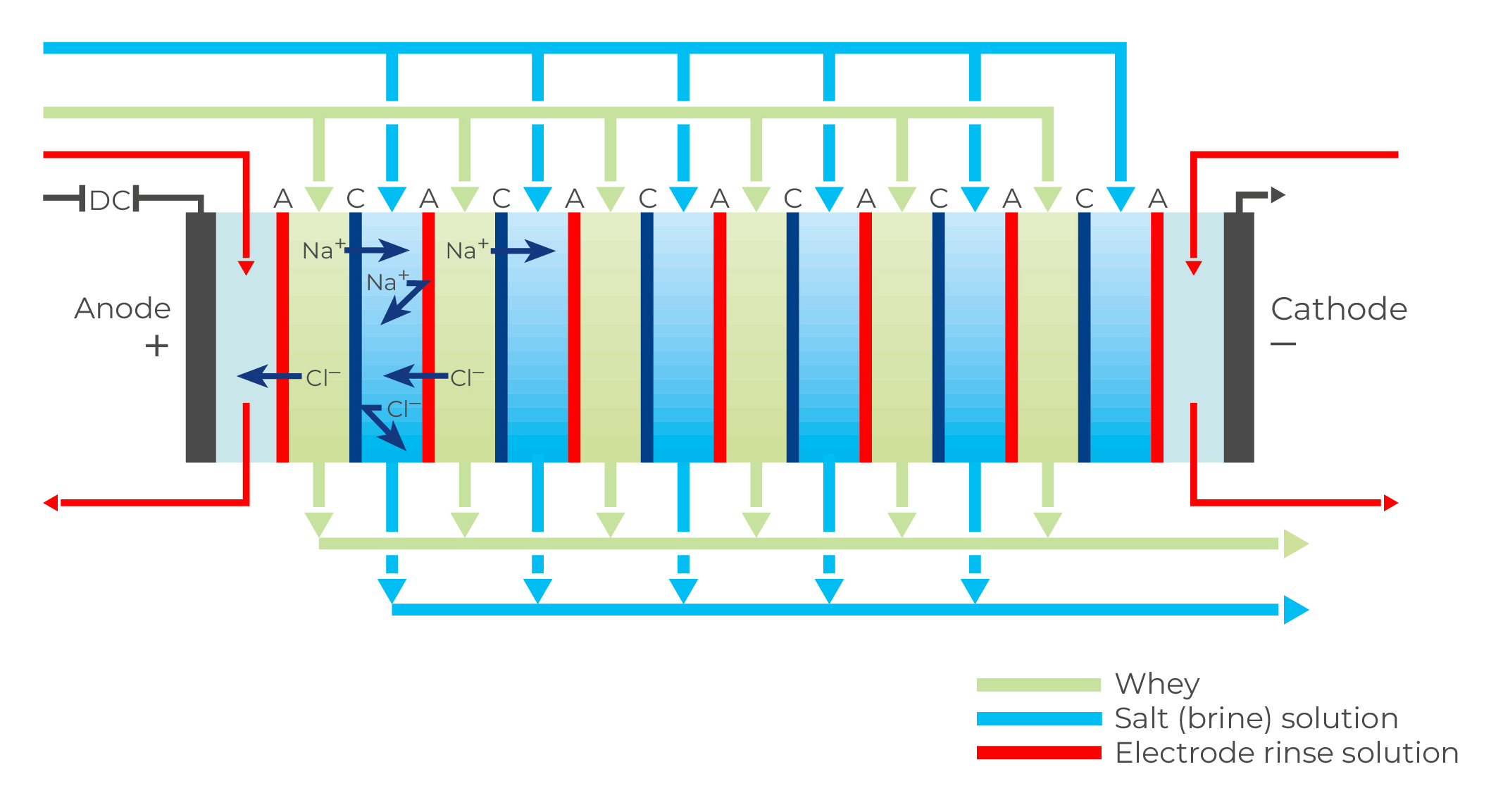
Fig. 18.12 Cell packs for electrodialysis.
A = Anions = positively charged
C = Cations = negatively charged
DC = Direct Current
Operating principle
Alternate cells in the electrodialysis stack act as concentration and dilution cells, respectively. Whey or UF permeate is circulated through the dilution cells and a 5% brine carrier solution is circulated through the concentration cells.
When direct current (DC) is applied across the cells, cations attempt to migrate to the cathode and anions to the anode, as shown in Figure 18.12. However, a completely free migration is not possible because the membranes act as barriers to ions of identical charge. Anions can pass through an anion membrane but are stopped by a cation membrane.
Conversely, cations can pass through a cation membrane but not an anion membrane. The net result is the depletion of ions in the product (whey/UF permeate) in the dilution cells. The product is thus demineralised, to an extent determined by the ash content of the product, residence time in the stack, current density and flow viscosity. The electrodialysis plant can be run either continuously or in batches. A batch system, which is often used for demineralisation rates above 70%, can consist of one membrane stack over which the process liquid, product, is circulated until a certain ash level is reached. This is indicated by the conductivity of the process liquid. The holding time in a batch system can be as long as 2 – 3 hours for 90% demineralisation at 10 – 15 °C. Pre-concentration of the product to 20 – 30% DM is desirable regarding capacity utilisation and electric power consumption. The product feed (whey/UF permeate) concentrate should be clarified before it enters the electrodialysis unit.
The process liquid heats up during the process, so a cooling stage is needed to maintain the process temperature. In a continuous plant, consisting of five membrane stacks in series, the holding time can be reduced to 10 – 40 minutes. The maximum demineralisation rate of such a plant is often limited to about 60 – 70%. In terms of capacity, the installed membrane area is much larger in a continuous plant than in a batch plant.
An electrodialysis plant can easily be automated and furnished with a programmed CIP system. The cleaning sequence normally includes a water rinse, cleaning with an alkaline solution (max. pH 9), a second water rinse, cleaning with hydrochloric acid (pH 1) and a final water rinse. A typical cleaning programme takes 100 minutes.
Power supply and automation
Direct current is used in the electrodialysis plant, which should have facilities for regulating current in the range of 0 – 185 amperes and voltage in the range of 0 – 400.
Voltage flow rates, temperatures, conductivity, pH of process water and product, product inlet pressure, pressure difference between the stacks and current, as well as voltage over each membrane stack, are monitored and controlled during production.
Limiting factors in electrodialysis
A major limiting factor for using electrodialysis in dairy processing is the cost of replacing membranes, spacers and electrodes, which constitutes 35 – 40% of the total running costs in the plant. Replacement is necessary due to fouling of the membranes, which in turn is caused by:
- Precipitation of calcium phosphate on the cation exchange membrane surfaces
- Deposition of protein on the anion exchange membrane surfaces
The first problem can be handled by proper flow design over the membrane surface and regular acid cleaning. Protein deposits are the main factor in shortening the lifetime of the anion membranes. The background to this problem is as follows: at the normal pH of whey, the whey proteins can be regarded as large negative ions (anions) and move as such under the influence of the electrical field in the stack. These molecules, being too large to pass through the anion exchange membranes, are deposited as a thin protein layer on the faces of the anion exchange membranes in the whey compartments. Techniques such as polarity reversal can be used to dislodge these deposited materials from the membrane.
Although frequent high-pH cleaning removes most of the deposits, disassembly of the stack for manual cleaning is recommended at intervals of 2 – 4 weeks. The processing cost of electrodialysis depends very much on the de-mineralisation rate. Increasing the capacity in steps from 50% to 75% to 90% doubles the processing cost per step. This means that it is four times as expensive to demineralise product solids per kilo to 90% than it is to 50% because plant capacity is reduced at 90% demineralisation.
Water treatment, electric power, chemicals and steam account for the operating costs of a demineralisation plant. Wastewater treatment is a particularly heavy item. During production, lactose leaks through the membranes at a rate of 7 – 10% at 90% demineralisation. The phosphate removed from whey also accumulates in the waste stream. The cost of electric power amounts to 10 – 15% of the processing cost, while the chemicals used in the process, mainly hydrochloric acid, account for less than 5%. The cost of steam used for pre-heating the product and cooling costs for control of process temperature are 10 – 15%, depending on the de-mineralisation level.
Electrodialysis is best for demineralisation levels below 70% where it is very competitive compared to ion exchange.
Ion exchange
In contrast to electrodialysis, the process which removes ionisable solids from solutions on a continuous electro-chemical basis, an ion exchange process employs resin beads to adsorb minerals from the solution, in exchange for other ionic species. The resins have a finite capacity for this, so when they are completely saturated, the adsorbed minerals must be removed, and the resins regenerated before reuse. Normally, the resins are used in fixed columns of suitable design.
Ion-exchange resins are macromolecular porous plastic materials, formed into beads with diameters in the range of 0.3 to 1.2 mm for technical applications. Chemically, they act as insoluble acids or bases which, when converted into salts, remain insoluble. The main characteristic of ion-exchange resins is their capacity to exchange the mobile ions they contain for ions of the same charge sign contained in the solution to be treated. A simple example of this reaction is shown for sodium chloride removal, where R is the exchange group bound to the insoluble resin.
Anion exchange R – OH + Cl– = R – Cl + OH– resin in OH– form
The reaction above is deliberately written as an equilibrium because the direction in which the reaction goes depends on the ion concentration in the liquid and in the solids phase of the resin. The equilibrium is characterised by a constant. On regeneration, the reaction is reversed when the sodium-laden ion-exchange resin is treated with, for example, a 4% hydrochloric acid solution.
The high concentration of hydrogen ions in the acid drives the equilibrium to the left.
The equilibrium constant varies depending on ion species, which gives the selectivity of ion exchange processes. Generally speaking, multivalent ions have higher selectivity than monovalent ones and ions of the same valence are selected by size, with large ions having higher selectivity. For cations typically found in dairy process streams, selectivity decreases in the order Ca2+ > Mg2+ > K+ > Na+.
Similarly, anion exchange selectively can be classified in the following way: citrate3– > HPO42– > NO3– > Cl–.
ln practice, this means that the ion exchanger, after being exhausted by a liquid containing different ion species will exist in different forms along the length of the column, as described in Figure 18.13. This figure shows what happens in a column treating ordinary raw water in a cation exchanger loaded in the hydrogen ion form. The situation after regeneration with acid is also shown. It can be seen that the ions that remain longest in the cation-exchange column are Na ions. This can be understood from the selectivity order described above. Returning to the picture of the exhausted cation-exchange column in the figure, the segregated distribution of ions means that Na ions leak first, followed by Mg2+ and Ca2+ ions. An initial ion leakage in the exhaustion phase may occur when the ion exchanger is not fully regenerated, but after a while, the Na+ ions are eluted and replaced by H+ ions (see Figure 18.13). The status of the lower part of the ion exchanger determines the leakage of ions from the process liquid.
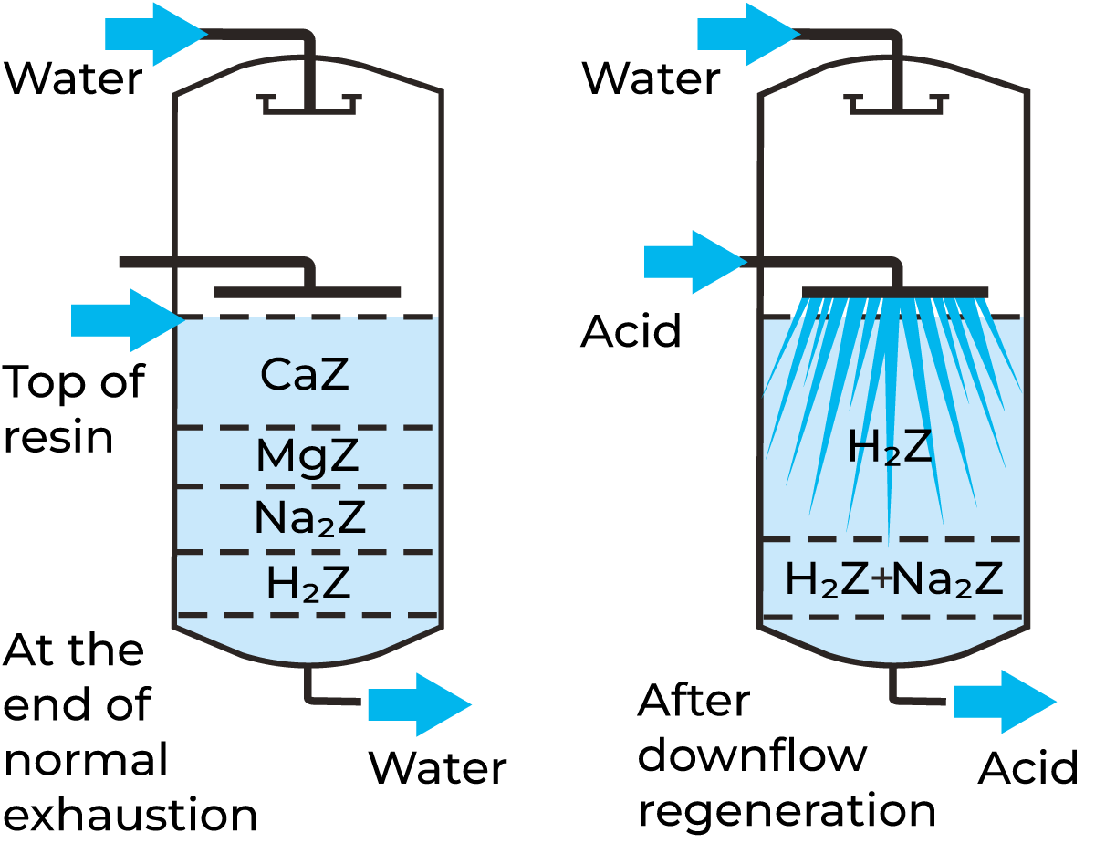
Fig. 18.13 Cation exchanger resin bed before and after regeneration with acid.
Ion-exchange resin characteristics
Ion-exchange resins in industrial use today are based on polymeric plastic materials to build up the porous matrix structure. Common materials are polystyrene/ divinyl benzene and polyacrylate. Functional groups are chemically bound to this matrix structure. Typical groups are:
- Sulphonic groups
-SO3-H+ (strong acid cation exchanger) - Carboxyl groups
-COO-H+ (weak acid cation exchanger) - Quatenary amine
N+ OH- (strong base anion exchanger) - Tertiary amines
NH+ OH- (weak base anion exchanger)
Both strong base and strong acid exchangers are fully ionised in the whole pH interval (0 – 14). Weak base and weak acid ion exchangers have a restricted pH area in which they are active. Weak acid cation exchangers cannot normally be used in the low pH range (0 – 7), because the carboxyl groups are mainly present in their free acid form, as determined by their acid/base dissociation constant (often expressed as pKa = –10 logarithm of the dissociation constant). At pH values higher than pKa the carboxylic groups are in their salt form and can consequently participate in ion exchange reactions. In contrast, weak base anion-exchange resins are only active in the low pH range, 0 – 7.
From the ease-of-regeneration point of view, it is beneficial to use weak resins whenever possible. They can be regenerated with acid/base respectively with an excess of only 10 – 50% of the theoretically needed amount. Strong resins require an acid/base excess of 300 – 400% compared with the theoretical value for regeneration. For demineralisation according to the classical procedure, a strong acid cation exchanger regenerated in the hydrogen form is combined with a weak base anion exchanger working in the free base (hydroxyl) form. It is not possible to use a weak acid cation exchanger instead of a strong one, because of the very advantageous equilibrium for exchange of cations for the hydrogen bound to the hydroxylic groups.
Other important characteristics of ion exchangers, which are not further discussed, are:
- Ion exchange capacity
- Swelling properties
- Mechanical strength
- Fluidisation during backflushing of the bed
- Pressure drop
- Flow-velocity restrictions
- Water rinse requirements after regeneration
Ion exchange processes for demineralisation
Demineralisation by ion exchange has long been an established process. Whey and UF permeate is not a uniform product in terms of composition. Whey from an acid casein/cheese curd has a pH of 4.3 – 4.6, while the pH of sweet whey is 6.0 – 6.6. The main difference between these two types of whey, apart from the acidifying medium, is the high level of calcium phosphate in the acid whey. It is good practice to use the cations as the base for calculating the salt load in whey because the anions, e.g. citrates and phosphates, are involved in proteolytic reactions. This complicates the calculation of specific ion contents. The figures for cation content are typical of sweet and acid whey respectively and are shown in table 18.1 and table 18.7.
Whey can consequently be characterised as a liquid with a high salt load which, as a consequence, results in short cycles when ion exchange is applied. This, in turn, results in high costs for regeneration chemicals, if they are not recovered.
Conventional ion exchange for demineralisation
A simple demineralisation plant using ion exchange is shown in Figure 18.14. The whey first enters the strong cation exchanger, loaded in H+ form, and continues to anion exchange in a weak base anion-exchanger in its free base form. The ion exchange columns are rinsed and regenerated separately with dilute hydrochloric acid and sodium hydroxide (ammonia). Once a day, the columns are disinfected with a small amount of active chlorine solution.
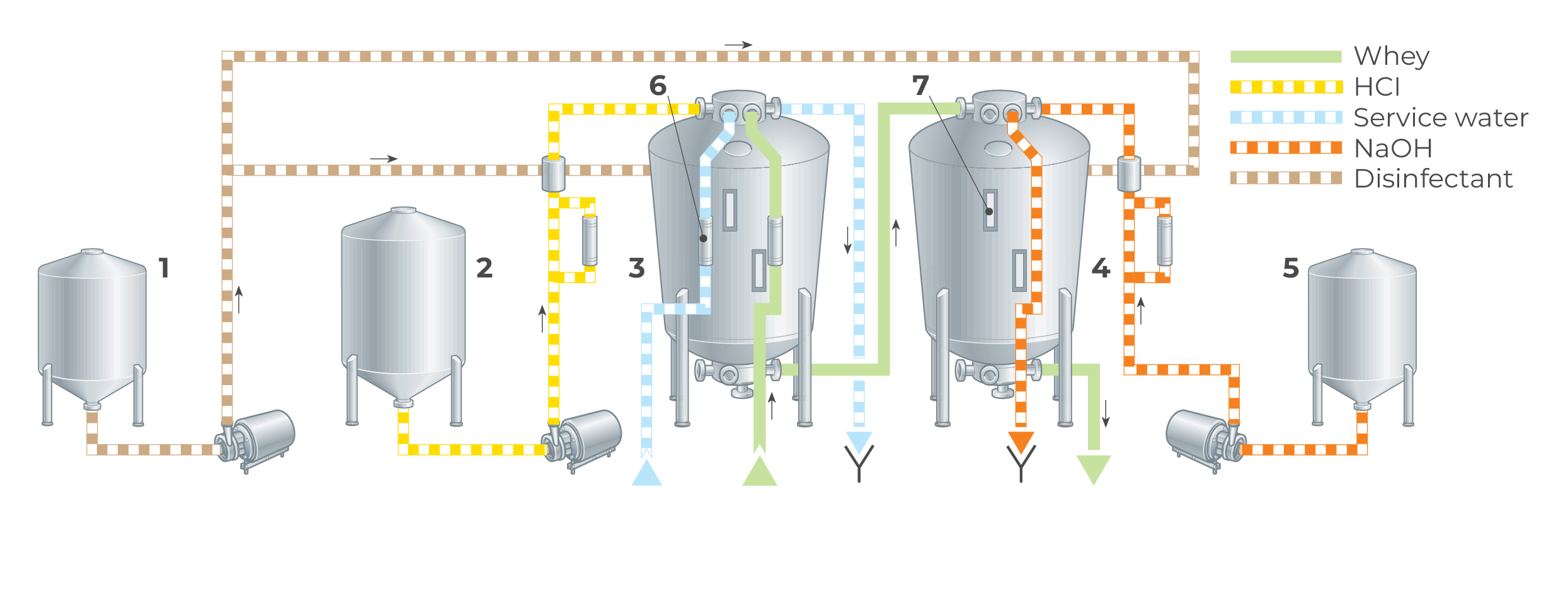
Fig. 18.14 Plant for demineralisation of cheese whey by classical ion exchange.
1. Disinfection tank
2. HCl tank
3. Cation tank
4. Anion tank
5. NaOH tank
6. Flow meter
7. Sight glass
The following net reactions take place during demineralisation (NaCI is used to illustrate the salts of whey and R represents the insoluble resin exchange site).
Anion exchange: R – OH + H+ + Cl– —— R – CI + H2O
The various flows in the ion exchange process include the following steps:
- Exhaustion 10 – 15 bed volumes of whey can be treated per regeneration. The bed volume is based on the bed volume of the cation exchanger.
- Regeneration
- Displacement of whey
- Backflushing
- Contact with regeneration solution
- Water rinse
The ion exchange columns are often made of rubber-lined mild steel, to avoid corrosion problems. The conical shape is used specially for the anion exchanger to allow for swelling of the bed, during transition from the free base form to the salt form. Counter-current flow is often used for regeneration of the cation exchanger. Thus, when whey is treated in downward flow, regeneration takes place in upward flow. This system reduces the consumption of regeneration chemicals by as much as 30 – 40% but at the expense of a more complicated design. The plant can easily be automated. Two or three parallel ion exchange systems are needed for a continuous flow of whey. A normal cycle time is six hours, four of which are used for regeneration.
Process limitations
Whey/UF permeate are liquids with high salt loads, which means short runs between regenerations. It also means a high consumption of regeneration chemicals and a high salt load in the waste from ash removal and the required surplus of regeneration chemicals. Rinse-water consumption is high too, especially for washing out excess sodium hydroxide from the weak anion resin.
Losses of whey proteins occur on the columns due to denaturation/absorption. This is caused by great pH variation in the whey during the ion exchange process. Consumption of regeneration chemicals accounts for 60 – 70% of the operating costs of the process.
The process is primarily designed for 90% demineralisation, but any demineralisation rate can be chosen if a bypass system is used. Different product mixes for whey solids to powder options are given in Figure 18.15.
Ion exchange chromatography; isolation of lactoperoxidase and lactoferrin
As briefly introduced in the last section on protein fractionation and concentration, IX chromatography can be used for this too. The use of natural bioactive agents is of great interest to producers of products like infant formulas, health foods, skin creams and toothpaste. IX chromatography can potentially separate also other whey proteins, but examples of such components are the bioactive proteins lactoperoxidase (LP) and lactoferrin (LF), which exist at low contents – typically 20 mg/l of LP and 35 mg/l (avg. 35 ppm, ranging 5 – 60 ppm) of LF – in whey. The LF content in milk is higher than in whey, ranging from 100 – 180 ppm. Ion exchange chromatography is usually used to isolate LP and LF from milk and whey as was briefly described in the section on protein fractionation and concentration.
The basic principle underlying the process is based on the fact that both LP and LF have isoelectric points in the alkaline pH area, which means that these proteins are positively charged at the normal pH of sweet whey (6.2 – 6.6). The rest of the whey proteins (e.g. β-lactoglobulin, a-lactalbumin and bovine serum albumin) are negatively charged in the same pH range. A fundamentally suitable process for the isolation of LP and LF is therefore to use a specially designed cation-exchange resin for selective adsorption. The LP and LF molecules thus bind to the negatively charged functional group of the cation exchanger by charge interaction, leading to the fixation of these molecules on the ion-exchange resin while the other whey proteins pass through because of their negative charge. To make the process industrially viable, some basic criteria must be satisfied.
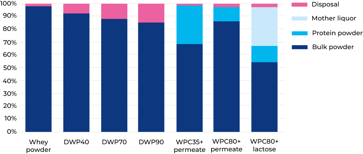
Fig. 18.15 Destination of the solids in whey for different product mix options.
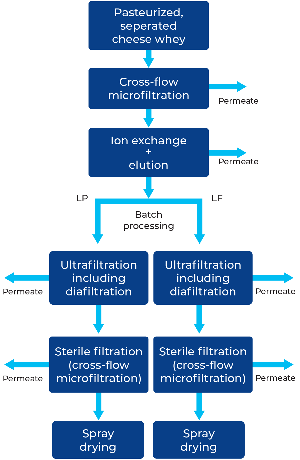
Fig. 18.16 Block diagram for isolation of lactoperoxidase (LP) and lactoferrin (LF) from milk and whey.
For whey, one of them is the need for a “particle-free” whey to maintain a high flow rate during the loading phase because very large volumes of whey have to pass the ion-exchange resin to achieve saturation. Crossflow microfiltration (MF) with a pore size of 1.4 μm, operated under a uniform transmembrane pressure (UTP), has proved to be a successful technique for getting particle-free whey. A stable flux of 1,200 – 1,500 l/m2h is easily sustained for 15 – 16 hours. This type of whey pre-treatment avoids the build-up of increasing back pressure over the ion exchange column.
The ion-exchange resin has a total capacity to adsorb 40 – 45 g of LP and LF per litre of resin before breakthrough occurs. With a resin bed volume of 100 l, almost 100,000 l of whey can be treated per cycle.
With properly chosen conditions for the elution of adsorbed bioactive proteins on the column, it is possible to obtain very pure fractions of LP and LF. Salt solutions of different strengths are used for this step. The proteins in the eluates occur in fairly concentrated form, of the order of 1% by weight. The ion exchange step thus concentrates LP and LF by a factor of almost 500 compared to the original whey. Further processing of the eluates by UF and diafiltration yields very pure protein products (approximately 95% purity). Finally, after sterile filtration in a crossflow microfilter with 0.1 – 0.2 μm pores, the protein concentrates are freeze-dried or spray-dried. The overall process is illustrated in Figure 18.16.
Lactose conversion
Lactose hydrolysis
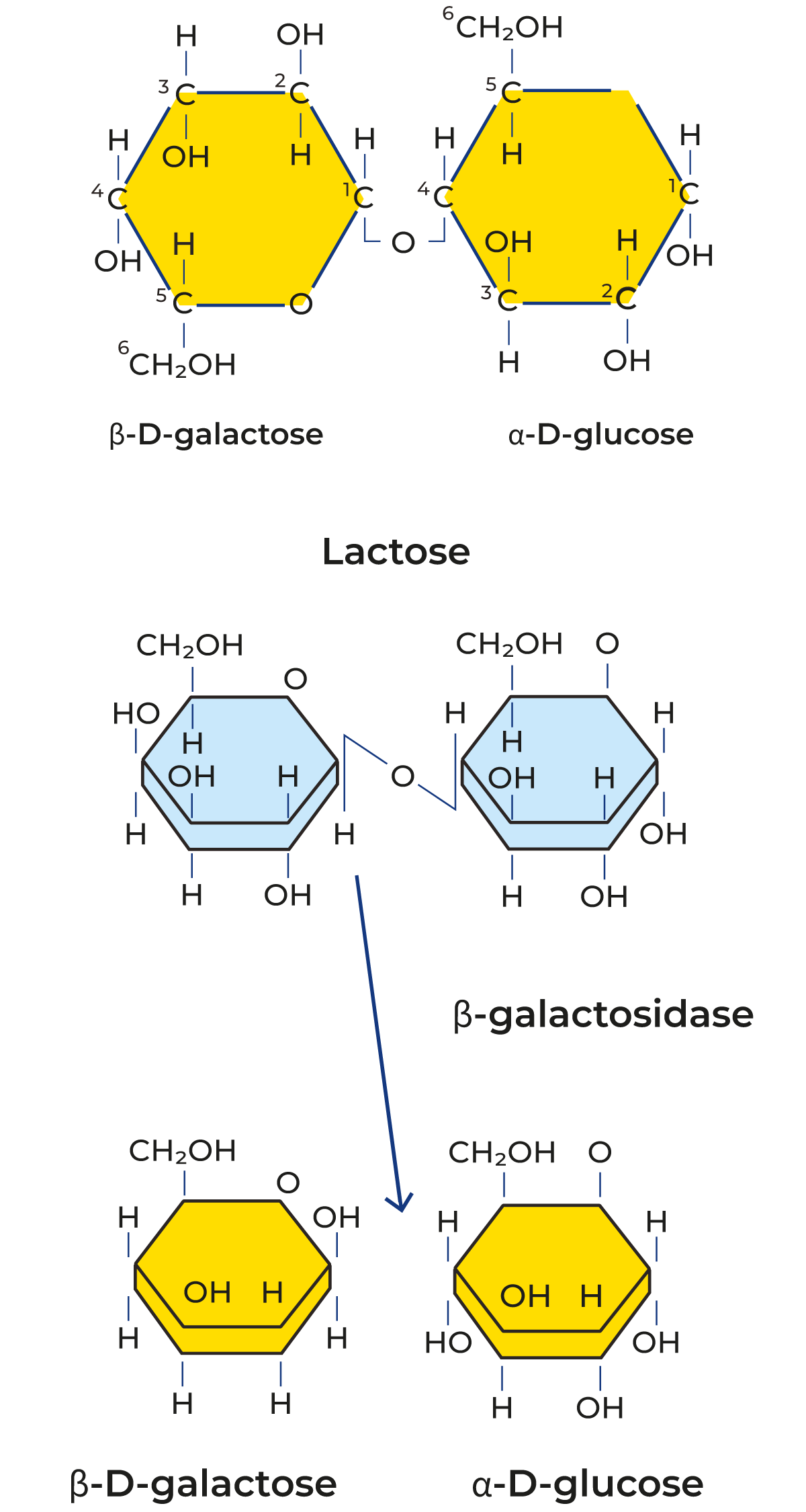
Fig. 18.17 Chemical structure of lactose and lactose splitting.
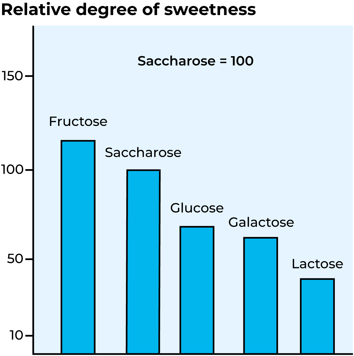
Fig. 18.18 Degree of sweetness of different types of sugar.
Lactose is a disaccharide consisting of the monosaccharides glucose and galactose, as shown in Figure 18.17. Lactose exists in two isomeric forms, a-lactose and β-lactose.
They differ in the spatial arrangement of the hydroxyl group at the C atom in the glucose molecule, and thereby also, amongst other things in:
- Solubility
- Crystal shape
- Melting point
- Physiological effect
Lactose can be split hydrolytically, i.e. by bonding of water or by an enzyme. The lactose-splitting enzyme β-galactosidase belongs to the hydrolase group. Figure 18.17 shows the enzymatic splitting of lactose into galactose and glucose. Lactose is not nearly as sweet as other types of sugar. Figure 18.18 indicates the relative degree of sweetness of different types of sugar. Hydrolysis of lactose consequently results in considerably sweeter products.
Some people lack the enzyme that decomposes lactose and therefore cannot drink or eat any significant quantities of milk products. This is called lactose intolerance. Hydrolysis of the lactose in the milk products allows these people to utilise the high-quality proteins, vitamins, etc. in milk products.
Some defects, such as sandy texture in ice cream (crystallisation of lactose) are practically eliminated by lactose hydrolysis.
Enzymatic hydrolysis
Figure 18.19 shows a process for enzymatic hydrolysis of lactose in whey.
Pre-treatment in the form of demineralisation is not essential, but it improves the taste of the final product. After hydrolysis, the whey is evaporated. A syrup with a dry solids content of 70 – 75% is then obtained. 85% of the lactose in this syrup is hydrolysed and can be used as a sweetener in the baking industries and the manufacture of ice cream.
During production, the enzyme is inactivated by heat treatment or by pH adjustment. It cannot be used again. Instead of using free enzymes, it is now possible to bind the enzyme to different types of water-soluble and non-water-soluble carriers. Such systems with immobilised enzymes can be used for continuous lactose hydrolysis. The enzyme, which is expensive, is not consumed and can be used to hydrolyse large amounts of product. This increases the profitability. The technique has not yet been developed to any great extent.
Other enzymatic conversions of lactose that require pre-treated purer lactose allow making galacto-oligosaccharides (GOS) a prebiotic product.
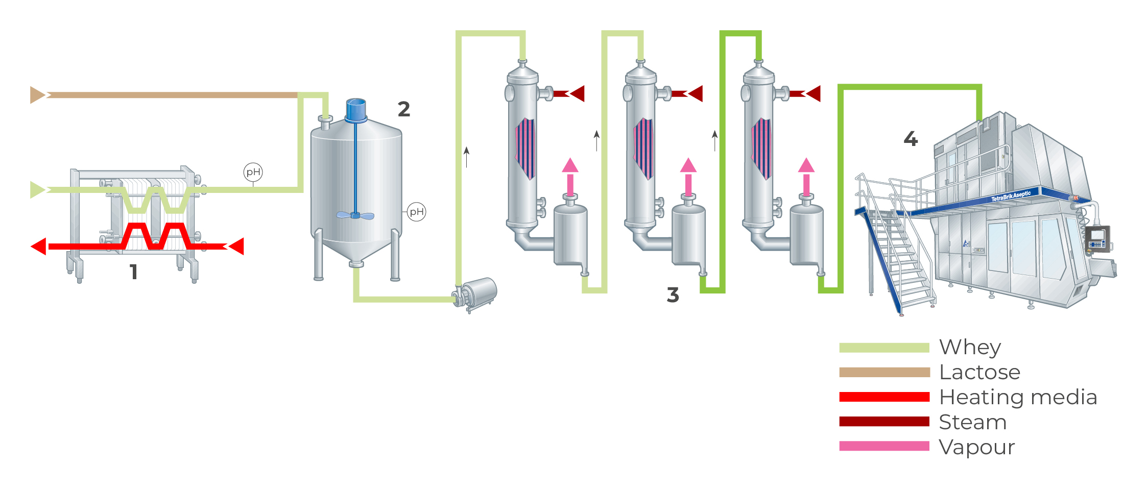
Fig. 18.19 Plant for enzymatic hydrolysis of lactose in whey.
1. Pasteurizer
2. Tank for hydrolysis
3. Evaporator
4. Filling
Acid hydrolysis
Lactose can also be split using acids in conjunction with heat treatment or by passing a cation exchanger in hydrogen form at high temperature, around 100 °C. The required degree of hydrolysis is determined by the selection of pH, temperature and holding time. As brown discolouration occurs during hydrolysis of the whey, active carbon treatment is recommended.
Chemical reaction
It has been established that non-protein nitrogen products can be used as partial replacement for natural protein in ruminants because certain microbes in the cattle rumen can synthesise protein from urea and ammonia. However, to get a balanced feed of nitrogen and energy, urea and ammonia have to be transformed into more suitable forms, which slowly release nitrogen to the rumen for improved protein synthesis.
Lactosyl urea and ammonium lactate are two such products based on whey.
Lactosyl urea
In brief, the procedure for production is as follows: after separation, the whey is concentrated up to 75% DM, typically in two steps. After the addition of urea and edible sulphuric acid, the whey concentrate is held at 70 °C for 20 hours in a jacketed tank provided with an agitator. Under these conditions, the urea reacts with the lactose to form lactosylurea.
Following the reaction period, the product is cooled and transported to a factory producing concentrated feed (pellets, for instance) or directly to farmers.
Ammonium lactate
The process technique involves fermentation of the lactose in whey into lactic acid and maintaining the pH with ammonia, resulting in the formation of ammonium lactate. After concentration to 61.5% DM, the product is ready for use.
References
de Wit, J.N. (2001) Lecturer’s handbook on whey and whey products. Association of Agricultural and Food Sciences in Medicine.
Walstra, P. (1999). Dairy Technology: Principles of Milk Properties and Processes (1st ed.). CRC Press. Available at: https://doi.org/10.1201/9780824746414
McSweeney, P.L.H. and O’Mahony, J.A. (eds) (2016) Advanced dairy chemistry, Vol. 1B: Proteins – Applied aspects. Available at: https://link.springer.com/ book/10.1007/978-1-4939-2800-2