DAIRY EFFLUENT
Water used in domestic and industrial applications can become polluted to varying degrees. Water is also used as a transport medium to carry away waste products. As awareness of the importance of improved standards of water treatment grows, process requirements become increasingly exacting. The food industry contributes significantly to pollution, particularly as the pollutants are of organic origin. Organic pollutants normally consist of 1/3 dissolved, 1/3 colloidal and 1/3 suspended substances, while inorganic materials are usually present mainly in solution.
Organic pollutants
The normal way to express the concentration of a pollutant is to specify the total quantity per unit volume of sewage. Another, more modern way of analysing the presence and quantities of organic substances in sewage effluent is the use of chromatography, such as high-performance liquid chromatography (HPLC).
However, the quantity of organic substances is normally determined in the form of:
- Biological oxygen demand (BOD)
- Chemical oxygen demand (COD)
- Calcining loss
- Total organic carbon (TOC)
Biological oxygen demand (BOD)
BOD is a measure of the content of biologically degradable substances in sewage. The substances are broken down by microorganisms in the presence of (and therefore with the consumption of) oxygen. Oxygen demand is measured in terms of the quantity of oxygen consumed by microorganisms over a period of five days (BOD5) or seven days (BOD7), in decomposing the organic pollutants in wastewater at a temperature of 20 °C. BOD is measured in mg oxygen/l or g oxygen/m3.
The following relationship is assumed for municipal sewage: BOD7 = 1.15 x BOD5
Chemical oxygen demand (COD)
COD indicates the quantity of pollutants in wastewater that can be oxidised by a chemical oxidant. The normal reagents used for this purpose are strongly acid solutions (to ensure complete oxidation) of potassium dichromate or potassium permanganate at high temperature. Consumption of oxidant provides a measure of the content of organic substance and is converted to a corresponding quantity of oxygen, expressing the result as mg oxygen/l or g oxygen/m3.
The COD/BOD ratio indicates how biologically degradable the effluent is. Low values, i.e. < 2, indicate relatively easily degradable substances, while high values, i.e. > 4, indicate the contrary. However, this relationship cannot be used generally, but a typical value of COD/BOD for municipal sewage effluent is often < 2.
In the FIL-IDF Bulletin about Dairy Effluents, Document 138, 1981, reported (Doedens) that the COD/ BOD5 ratio for effluent generated in different groups of dairies producing liquid milk, butter or cheese ranged from 1.16 to 1.57, at an average of 1.45. In other groups of dairy plants producing milk powder, whey powder, lactose and casein, the ratio varied from 1.67 to 2.34, with an average of 2.14. However, the general conclusion of the FIL-IDF Bulletin was that a COD:BOD ratio established in one dairy plant could not be transferred with sufficient reliability to another plant.
Calcining loss
Calcining loss is obtained by first determining the dry solids content in a sample, and then calcining it so that the organic substance is burnt. The difference in weight before and after calcining represents the quantity of organic substance. The value is expressed as a percentage.
Total organic carbon (TOC)
TOC is another measure of the quantity of organic materials, determined by measuring the quantity of carbon dioxide produced from the combustion of a sample. The unit is mg/l.
Drinking water
The table below is extracted from Guidelines for drinking-water quality: fourth edition incorporating the first and second addenda, Geneva: World Health Organisation (WHO); 2022. The WHO's Guidelines for drinking-water quality also contain many other chemical and microbiological parameters which impact water quality.
Inorganic pollutants
The inorganic components of sewage consist almost entirely of salts and are determined largely by the ionic composition and salt concentration in the mains water. The presence of these salts in sewage is normally unimportant. Present-day effluent treatment processes concentrate on the reduction of nitrogen, phosphorus salts and heavy metals.
Nitrogen and phosphorus compounds are important, as they are nutrients for organisms, e.g. algae, in recipients. As a result of the growth of algae, secondary processes can proceed in the recipient, forming further organic substances which, when they decompose, can result in considerably higher oxygen demand than is caused by primary organic pollutants in the sewage effluent.
Heavy metals may be toxic in high concentrations and may also disturb ecosystems in low concentrations.
Dairy wastewater
Dairy wastewater can be divided into three categories:
- Cooling water
- Sanitary wastewater
- Industrial wastewater
Cooling water
As cooling water is normally free from pollutants, it is discharged into the stormwater piping system, the system for run-off water from rain and melting snow, etc.
Sanitary wastewater
The sanitary wastewater is normally piped directly to the sewage treatment plant with or without first being mixed with industrial wastewater.
Industrial wastewater
Industrial wastewater emanates from spillage of milk and products thereof, and from cleaning of equipment that has been in contact with milk products. The concentration and composition of the waste depend on the production programme, operating methods and the design of the processing plant.
Sewage treatment plants are dimensioned to treat a certain quantity of organic substances and also to be able to deal with certain peak loads. However, one organic substance – fat – presents particularly difficult problems. Besides having a high BOD (cream with 40% fat has a BOD5 of about 400,000 mg oxygen/l while skim milk has 70,000 mg/l), fat sticks to the walls of the mains system, as well as causes sedimentation problems in the sedimentation tank as it rises to the surface.
Dairy wastewater should therefore pass through a floatation plant where it is aerated with "dispersion water". The method of supplying finely dispersed air bubbles to the water at a pressure of 400 – 600 kPa is called dissolved-air flotation. The air bubbles attach themselves to the fat, carrying it rapidly to the surface where it is strained off, manually or mechanically, depending on the size of the plant. The flotation plant is often located close to the dairy building and the waste passes through it in a continuous flow.
The defatted effluent can then be mixed with the sanitary wastewater going to the sewage treatment plant. Table 23.2 lists the BOD of some milk products.
pH of dairy effluent
The pH of dairy effluent varies between 2 and 12, as a result of the use of acid and alkaline detergents for plant cleaning.
Both low and high pH values interfere with the activity of the microorganisms that break down organic pollutants in the biological treatment stage of the sewage treatment plant, transforming them into biological sludge (cell detritus). As a rule, wastewater with a pH of over 10 or below 6.5 must not be discharged into the sewage system, as it is liable to corrode the pipes. Used detergents are therefore normally collected in a mixing tank, often located close to the cleaning plant, and the pH is measured and regulated to about pH 7.0 before it is discharged to the drain.
WWTP stands for Wastewater Treatment Plant.
Reducing the quantity of pollutants in waste water
There are many solutions for minimising the amount of pollutants in dairy wastewater. Closed systems, reuse and recovery of water, and recirculation of product/water mixture over membrane filters are just a few examples of how to reduce pollutants in wastewater. In many dairy plants, ultrafiltration and microfiltration are used for the purification and reuse of CIP solutions. Condensation water from evaporators can preferably be reused for other purposes in the plant.
It is constantly necessary to control and prevent the wastage of water and product in the processing plant. Hidden losses of water in subfloor and underground piping can be detected by reading the water meter and recording the quantity used at the end of the day.
Daily records of water consumption should then be compared with the daily quantity of milk that has been processed. Water consumption, expressed as cubic metres per tonne of treated milk, should be plotted on a graph kept in an easily accessible place. A typical water-to-milk ratio is 2:1, but with intense saving of water, it is possible to come down to a ratio of less than 1:1.
The following general recommendations can serve as a guide to reducing wastage of water and product:
General milk treatment
- In reception of milk, particularly when tankers are emptied, it is important that the outlet from the tankers is at least 0.5 m above the receiving container or tank, and that the connecting hose is well stretched, to ensure that the tankers are completely drained.
- All pipelines must be identified and marked, to avoid wrong connections that would result in unwanted mixing of products, as well as leakage of milk.
- When pipes are installed, they should be laid with a slight and correctly calculated gradient to make them self-draining. In addition, the pipes must be well supported to prevent vibration, which could cause the couplings to work loose and thus cause leakage.
- All tanks should be equipped with level controls to prevent overflow. When the highest permitted level is reached, either the feeding pump is automatically stopped and the plant operator notified, or an automatic valve system is activated to route the product to another pre-selected tank.
- It is better to prevent the wastage of product than to flush it away with a hose afterwards. Try to keep the floors dry; this also makes leaks easier to detect.
- Make sure that the piping system and tanks are properly emptied before they are rinsed out with water.
- Check that the couplings are airtight; if air leaks into the piping system, it will cause increased burning-on in heaters, erosion problems in homogenizers and foaming in milk and cream tanks (which will then be harder to empty completely).
Cheese production area
- Make sure that open cheese vats are not filled to the top; stop filling when the milk level is at least 10 cm below the rim.
- Collect whey carefully and try to find commercial uses for it instead of discharging it as waste.
- Curd on the floor should be swept up and treated as solid waste – not flushed into the gutter with water.
Butter production area
- Cream and butter stick more readily than milk to surfaces they come in contact with and will aggravate the contamination of wastewater unless they are removed before cleaning starts.
- After the end of a butter production run, all accessible surfaces should be manually scraped clean.
- Cream and remaining butter can then be removed with steam and hot water and collected in a container for separate treatment.
Milk powder production area
- The evaporators should be run at the lowest possible level to prevent overcooking.
- Re-use the condensate as cooling water after circulation through a cooling tower or as feed water to the boiler.
- Spilled dry products should be swept up and treated as solid waste.
Milk packaging area
- The filling machines can be provided with drains discharging into one or more containers.
- Returned packages can be emptied into containers and the mixture of sweet and sour liquids used as animal feed.
Outlet control
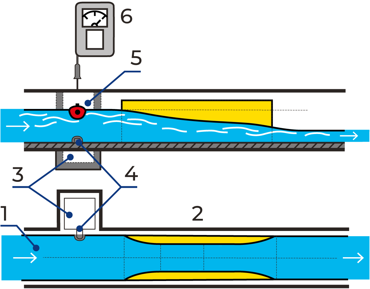
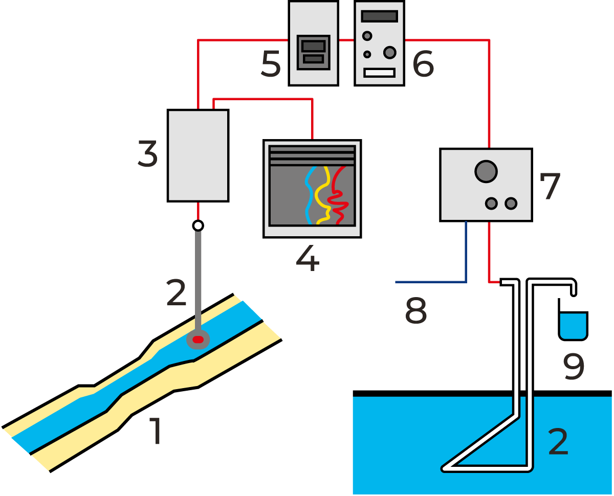
Disposal of wastewater is subject to regulation in many countries. Outlet control, for example, must be arranged so that the volume of wastewater is continuously measured and recorded and an aliquot part, in proportion to the volume of the flow, is sampled.
Figure 23.1 illustrates a system for measuring the flow in an open canal with a venturi flume. For information about the venturi flume and other measuring systems, please contact the municipal authorities dealing with sewage water treatment. As for sampling, one example of the procedure is shown in Figure 23.2.
Signals indicating the volume of water measured in the flume are transmitted via a control unit to the sampling device. An aliquot volume of the flow is sampled whenever a pre-determined volume of water, e.g. 100 l, has passed the flow transmitter. The daily samples are mixed, and after an optional period, a smaller volume of the mixed samples is analysed.
Sewage treatment, a general survey
Various arrangements are possible; the choice of treatment is determined by the required degree of pollutant reduction. Figure 23.3 shows four possible systems. When planning a new plant, contact the local authorities at an early stage for a discussion about effluent treatment and sewage BOD or/and COD levels.
Sewage treatment, in its original form, consisted simply of removing the bulk of solid impurities by mechanical sedimentation (A). When this treatment was judged to be insufficient, it was supplemented with biological treatment (B) to decompose the organic compounds.
Many sewage treatment plants were later extended with a third stage for chemical treatment (C) when the emission of phosphorus became a serious problem. The process in plants of this type is called post-precipitation because the chemical precipitation step comes last.
Later experience has, however, proved that it is possible to obtain the same result if chemical precipitation is combined with mechanical treatment in the first step. This system is called pre-precipitation (see Figure 23.3.2).
This arrangement also represents a major rationalisation of the process, as most of the sewage treatment is done in one step. The phosphorus content is already reduced by 90% and the BOD by 75% in the pre-sedimentation basins. As a result, the biological stage has a much lighter load to deal with and requires a lower basin volume less energy.
1. Post-precipitation
Conventional three-stage process with A mechanical, B biological, and C chemical treatment. Effective and reliable, but fairly expensive.
2. Pre-precipitation
A two-stage process developed during the 1980s. C chemical treatment is combined with A mechanical sedimentation in the first stage, which results in high-grade phosphorus reduction as well as about 70% BOD reduction. This relieves the load on the B biological stage, which thus requires a much lower basin volume and energy than with conventional post-sedimentation.
3. Direct precipitation
A single-stage process, with combined A mechanical and C chemical treatment as in pre-precipitation, but with no succeeding biological treatment stage.
4. Simultaneous precipitation
A two-stage process with A mechanical treatment followed by a combined B/C biological-chemical stage. A fairly cheap method of satisfying the demand for phosphorous reduction without expensive additional basin capacity, but less efficient than if the biological and chemical treatments are performed separately.
Mechanical treatment
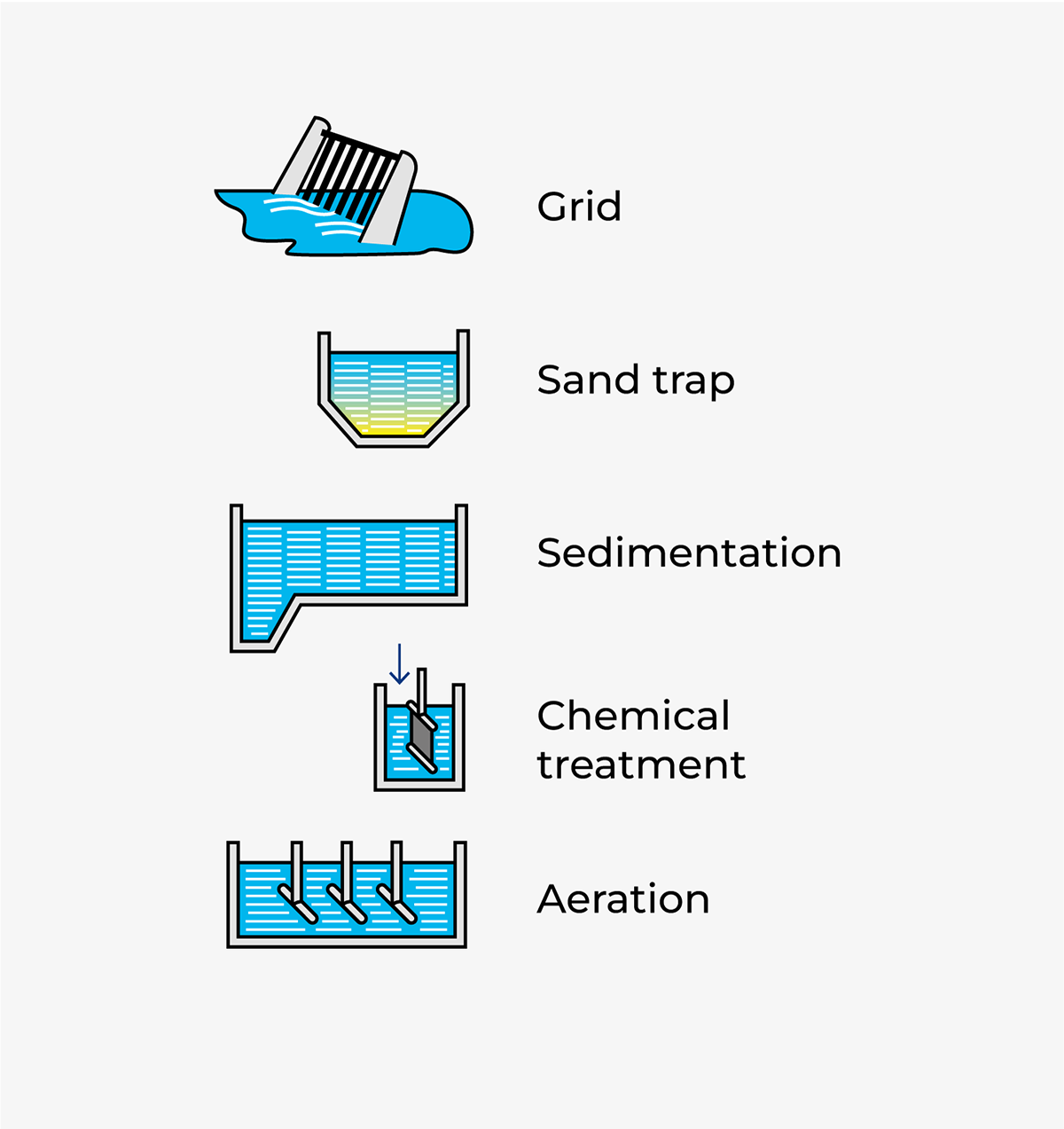
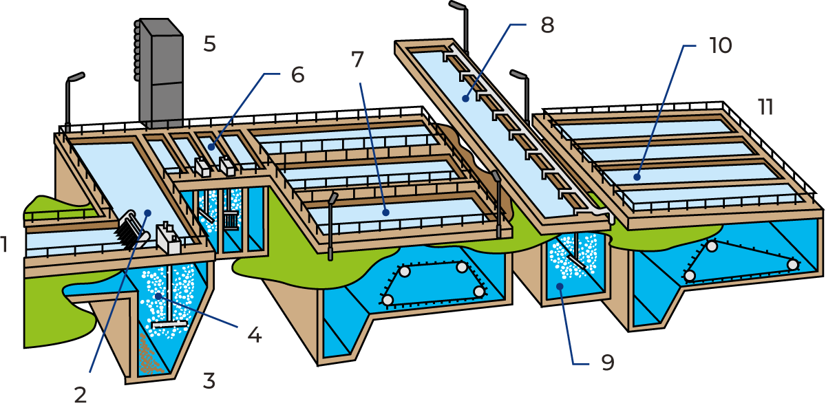
The primary (mechanical) stage of sewage treatment comprises a strainer grid, sand trap and primary sedimentation basins.
The grid traps coarse solid matter: plastic, rags, food residues, etc. This matter is continuously scraped off the grid and disposed of separately, usually as landfill.
The sand trap is a basin in which coarse separation takes place. It is dimensioned and operated in such a way that sand and other heavy particles have time to settle to the bottom, while fat and other impurities that are lighter than water float to the surface. The sediment is pumped away, and the floating scum is removed by scrapers. These waste products are likewise disposed of separately.
Air is blown into the sand trap, partly to keep finer particles in suspension and partly to prevent putrefaction processes that cause bad smells.
Chemical treatment
The principal purpose of chemical sewage treatment, also known as precipitation, is to rid the water of phosphorus. Municipal sewage systems normally collect 2.5 – 4.0 grams of phosphorus per person per day, mainly in the form of phosphates. Detergents account for about 30% of the phosphate content; the remaining 70% comes mainly from human excreta and food residues.
Chemical precipitation with iron and aluminium-based flocculants can remove almost 100% of the phosphorus present in wastewater, while conventional biological treatment only reduces the phosphorus content by 20 – 30%.
The precipitation stage starts with flocculation tanks, where the flocculants are added and vigorously mixed into the water by agitators. This results in precipitation of insoluble phosphates, initially in the form of very fine particles which gradually aggregate into larger flocs. The flocs settle out in pre-sedimentation basins, from which a clear effluent overflows into the basin for biological treatment.
Pre-sedimentation is the final step in the combined mechanical and chemical treatment. The water is allowed to flow slowly through one or more basins where the finer particles gradually settle to the bottom as primary sludge.
The sedimentation basins are equipped with devices that continuously scrape the sediment into a sump and transverse gutters that carry off water from the clarified surface layer.
Biological treatment
The remaining organic impurities in the “overflow” from the chemical treatment are broken down with the help of microorganisms e.g. bacteria, which feed on the organic substances present in the water.
The microorganisms must have access to oxygen to perform their function. This is supplied in the form of air blown into the aeration basin.
The microorganisms reproduce continuously, forming an active sludge. This sludge is removed from the water by settling in post-sedimentation basins. Most of it is recirculated to the aeration basins to keep the biological breakdown process going; the excess sludge is removed from the process for further treatment and the clarified effluent is discharged to the recipient.
An alternative to the aeration basin is the biological filter, which is a container filled with pieces of stone or plastic. The water is sprinkled over the filter by a rotating distributor. It then trickles down through the filter bed and is oxygenated by air circulation. A “skin” of microorganisms builds up on the surfaces of the stones, etc., breaking down the organic impurities in the water.
Sludge treatment
Since the beginning of 1990s, the development of sludge treatment has been in focus. In some countries, there has been a demand for thermophilic treatment of the sludge at 70 – 75 °C in order to destroy harmful microorganisms.
The sludge from the various stages of treatment is collected in thickening tanks to which chemicals are added to facilitate further aggregation of the solid particles.
To further break down organic matter and to reduce foul-smelling substances, the sludge is eventually pumped into a digester where the organic substancesare broken down under anaerobic conditions into carbon dioxide and methane and very small amounts of hydrogen gas, ammonia and hydrogen sulphide.
Carbon dioxide and methane are the main components of digester gas, which can be utilised as fuel for heating.
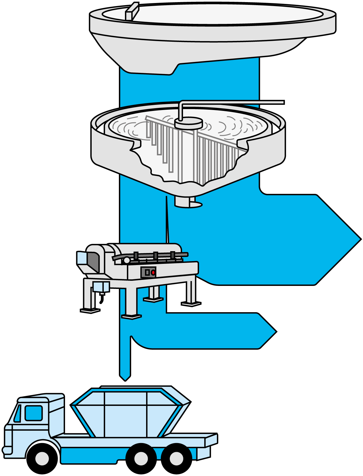
Digester sludge is a homogeneous, practically odourless, dark-coloured substance which still has a high moisture content of around 94 – 97%. It is therefore dewatered, most effectively in a decanter centrifuge, which discharges a solid phase of about one-eighth of the original volume, as shown in Figure 23.5.
The dewatered sludge can then be utilised as fertiliser or landfill, or simply deposited as waste. The sludge can be an integrated part of the cultivation of energy forest (e.g. Salix) as the sludge contains lots of valuable nutrition for crops.
