Heat exchangers
The purposes of heat treatment
By the end of the 19th century, heat treatment of milk had become so commonplace that most dairies used the process for some purpose or another, such as for milk intended for cheese and butter production.
Before heat treatment was introduced, milk was a source of infection, as it is a perfect growth medium for microorganisms. Diseases such as tuberculosis and typhus were sometimes spread by milk.
The term “pasteurization” commemorates Louis Pasteur, who in the middle of the 19th century made his fundamental studies of the lethal effect of heat on microorganisms and the use of heat treatment as a preservative technique. The pasteurization of milk is a special type of heat treatment, which can be defined as “any heat treatment of milk that secures the certain destruction of harmful bacteria that can lead to diseases, without markedly affecting the physical and chemical properties of the milk”.
In considering the history of pasteurization it is worth mentioning that although scientists everywhere agreed fairly closely on the necessary degree of heat treatment, the process was very loosely controlled in commercial practice for a long time. Milk was frequently either overheated or underheated so that it either had a cooked flavour or was found to contain viable T.B.
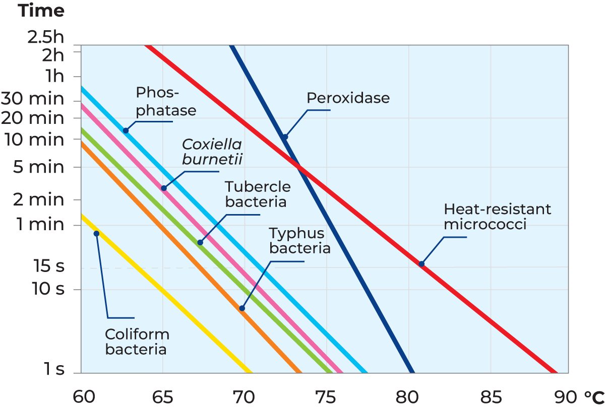
In the middle of the 1930s (JDR:6/191), Kay and Graham announced the detection of the phosphatase enzyme. This enzyme is always present in raw milk and is destroyed by the temperature/time combination necessary for efficient pasteurization. In addition, its presence or absence is easily confirmed (Phosphatase test). The absence of phosphatase indicates that the milk has been adequately heated.
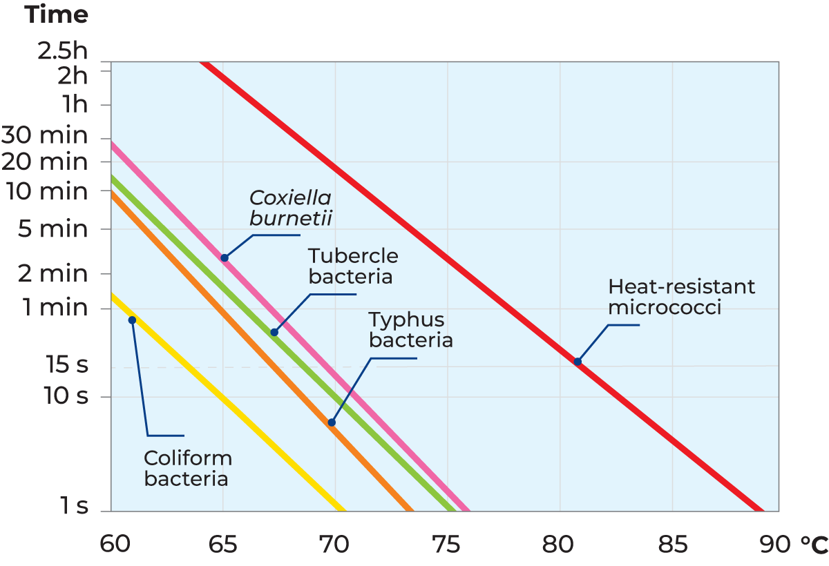
Fortunately, all common pathogenic organisms likely to occur in milk are killed by relatively mild heat treatment, which has only a very slight effect on the physical and chemical properties of milk. The most heat-resistant non-sporulating pathogen known today is Coxiella burnetii, which is considered to be killed by heating milk to 63 °C for 10 minutes. Complete safety can be assured by heating milk to 63 °C for 30 minutes. Coxiella burnetii is therefore regarded as the index organism for pasteurization: any heat treatment that destroys Coxiella burnetii can be relied upon to destroy all other pathogens in milk.
Apart from pathogenic microorganisms, milk also contains other substances and microorganisms that may spoil the taste and shorten the shelf life of various dairy products. Hence, a secondary purpose of heat treatment is to destroy as many as possible of these other organisms and enzymatic systems. This requires more intense heat treatment than is needed to kill the pathogens.
This secondary purpose of heat treatment has become more and more important as dairies have become larger and less numerous. Longer intervals between deliveries mean that, despite modern cooling techniques, microorganisms have more time to multiply and develop enzymatic systems. In addition, the constituents of the milk are degraded, the pH drops, etc. To overcome these problems, heat treatment must be applied as quickly as possible after the milk has arrived at the dairy.
Time/temperature combination
The combination of temperature and holding time is very important, as it determines the intensity of the heat treatment. Figure 7.1.1 shows lethal effect curves for coliform bacteria, Typhus bacteria and Coxiella burnetii. According to these curves, coliform bacteria are killed if the milk is heated to 70 °C and held at that temperature for about one second. At a temperature of 65 °C it takes a holding time of 10 seconds to kill coliform bacteria. These two combinations, 70 °C/1 s and 65 °C/10 s, consequently, have the same lethal effect.
Tubercle bacilli are more resistant to heat treatment than coliform bacteria. A holding time of 20 seconds at 70 °C or about 2 minutes at 65 °C is required to ensure that they are all destroyed. There might also be heat-resistant micrococci in milk, but as a rule, they are completely harmless.
Limiting factors for heat treatment
Intense heat treatment of milk is desirable from a microbiological point of view. But such treatment also involves a risk of adverse effects on the appearance, taste and nutritional value of the milk. Proteins in milk are denatured at high temperatures. This means that the cheesemaking properties of milk are drastically impaired by intense heat treatment. Intense heating produces changes in taste; first cooked flavour and then burnt flavour. The choice of time/temperature combination is therefore a matter of optimisation, in which both microbiological effects and quality aspects must be taken into account. Since heat treatment has become the most important part of milk processing, and knowledge of its influence on milk is better understood, various categories of heat treatment have been initiated, as shown in Table 7.1.1.
Thermisation
In many large dairies, it is not possible to pasteurize and process all the milk immediately after reception. Some of the milk must be stored in silo tanks for hours or days. Under these conditions, even deep chilling is not enough to prevent serious quality deterioration.
Many dairies therefore pre-heat the milk to a temperature below the pasteurization temperature, to temporarily inhibit bacterial growth. This process is called thermisation. The milk is heated to 63 – 65 °C for about 15 seconds, a time/temperature combination that does not inactivate the phosphatase enzyme. Double pasteurization is forbidden by law in many countries, so thermisation must stop short of pasteurization conditions.
To prevent aerobic spore-forming bacteria from multiplying after thermisation, the milk must be rapidly chilled to 4 °C or below and it must not be mixed with untreated milk. Many experts are of the opinion that thermisation has a favourable effect on certain spore-forming bacteria. The heat treatment causes many spores to revert to the vegetative state, which means that they are destroyed when the milk is subsequently pasteurized.
Thermisation should be applied only in exceptional cases. The objective should be to pasteurize all the incoming milk within 24 hours of arrival at the dairy.
LTLT pasteurization
The original type of heat treatment was a batch process in which milk was heated to 63 °C in open vats and held at that temperature for 30 minutes. This method is called the holder method or low temperature, long time (LTLT) method. Nowadays milk is almost always heat treated in continuous processes like thermisation, HTST pasteurization or UHT treatment.
HTST pasteurization
HTST is the abbreviation of High Temperature Short Time. The actual time/temperature combination varies according to the quality of the raw milk, the type of product treated, and the required storage properties.
Milk
The HTST process for milk involves heating it to 72 – 75 °C with a hold of 15 – 20 seconds before it is cooled. The phosphatase enzyme is destroyed by this time/temperature combination. The phosphatase test is therefore used to check that milk has been properly pasteurized. The test result must be negative; there must be no detectable phosphatase activity (Figure 7.1.2).
Cream and cultured products
Phosphatase tests should not be used for products with fat contents above 8%, as some reactivation of the enzyme takes place a fairly short time after pasteurization. The heat treatment must also be stronger, as fat is a poor heat conductor.
Peroxidase, another enzyme, is therefore used for checking the pasteurization results for cream (Peroxidase test according to Storch). The product is heated to a temperature above 80 °C, with a holding time of about five seconds. This more intense heat treatment is sufficient to inactivate peroxidase. The test must be negative – there must be no detectable peroxidase activity in the product (Figure 7.1.2).
As the phosphatase test cannot be used for acidified products either, heating control is based on the peroxidase enzyme. Milk intended for cultured milk production is normally subjected to intense heating to coagulate whey proteins and increase its water-binding properties, i.e. prevent the formation of whey.
Ultra pasteurization
Ultra pasteurization can be utilised when a particular shelf life is required. For some manufacturers, two extra days are enough, whereas others aim for a further 30 – 40 days on top of the 2 – 16 days that are traditionally associated with pasteurized products. The fundamental principle is to reduce the main causes of reinfection of the product during processing and packaging, so as to extend the shelf life of the product. This requires extremely high levels of production hygiene and a distribution temperature of no more than 7 °C – the lower the temperature, the longer the shelf life.
Heating milk to 125 – 138 °C for 2 – 4 seconds and cooling it to < 7 °C is the basis of extended shelf life. ESL, Extended Shelf Life, is a general term for heat-treated products that have been given improved keeping qualities by one means or another. Nevertheless, ESL products must still be kept refrigerated during distribution and in retail stores.
UHT treatment
UHT is the abbreviation for Ultra High Temperature. UHT treatment is a technique for preserving liquid food products by exposing them to brief, intense heating, normally to temperatures in the range of 135 – 140 °C. This kills microorganisms that would otherwise destroy the products.
UHT treatment is a continuous process that takes place in a closed system that prevents the product from being contaminated by airborne microorganisms. The product passes through heating and cooling stages in quick succession. Aseptic filling, to avoid reinfection of the product, is an integral part of the process.
Two alternative methods of UHT treatment are used:
- Indirect heating and cooling in heat exchangers,
- Direct heating by steam injection or infusion of milk into steam and cooling by expansion under vacuum.
Sterilisation
The original form of sterilisation, which is still in use, is in-container sterilisation, usually at 115 – 120 °C for some 20 – 30 minutes.
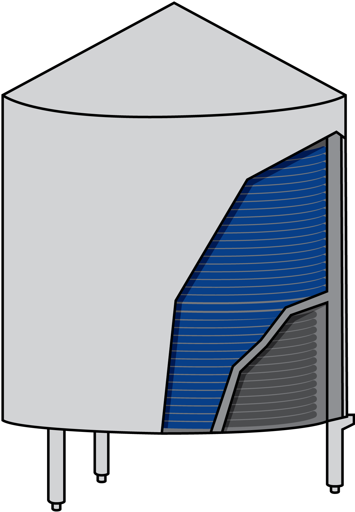
After fat standardization, homogenization and heating to about 80 °C, the milk is packed in clean containers, usually glass or plastic bottles for milk, and cans for evaporated milk. The product, still hot, is transferred to autoclaves in batch production or to a hydrostatic tower in continuous production.
Pre-heating
Normally, the desired processing temperatures are reached directly after pasteurization, but sometimes it is necessary to cool and store the milk temporarily before the final processing is done. Some examples are given below.
Cheese milk is pre-heated to 30 – 35 °C prior to the vat, where a final temperature adjustment is made before the rennet is added. Hot water is used as the heating medium. Warm whey from a previous batch can also be utilised for a first pre-heating step, in order to cut the heating costs.
Yoghurt milk is pre-heated to 40 – 45 °C prior to the fermentation tank, where the addition of culture takes place. Hot water is used as the heating medium.
Milk can also be pre-heated before the addition of other ingredients, (such as chocolate powder, sugar or fats), in the manufacture of different milk-based food products.
Heat transfer processes in the dairy
One of the most important requirements of modern dairying is to be able to control the temperature of products at every stage in the process. Heating and cooling are therefore very common operations in the dairy.
Heating
Hot water, or occasionally low-pressure steam, is used as the heating medium to heat milk. A certain amount of heat is transferred from the heating medium to the milk so that the temperature of the latter rises, and the temperature of the heating medium drops correspondingly.
Cooling
Directly after arrival at the dairy, the milk is often cooled to a low temperature (5 °C or lower), to
Heating and cooling are the most important operations in the dairytemporarily prevent the growth of microorganisms. Following pasteurization, the milk is also cooled again to about 4 °C.
If naturally cold water is at hand, it may be utilised for pre-cooling after pasteurization and regenerative heat exchange. In all cases, heat is transferred from the milk to the cooling medium. The temperature of the milk is reduced to the desired value and the temperature of the cooling medium rises correspondingly. The cooling medium may be cold water, ice water, brine solution or an alcohol solution, such as glycol.
Regenerative heating and cooling
In many cases, a product must first be heated for a certain treatment and then cooled. Pasteurization of milk is an example. Chilled milk is heated from perhaps 4 °C to a pasteurization temperature of 72 °C, held at that temperature for 15 seconds and then chilled to 4 °C again.
The heat of the pasteurized milk is utilised to heat the cold milk. The incoming cold milk is pre-heated by the outgoing hot milk, which is simultaneously pre-cooled. This saves heating and refrigeration energy. The process takes place in a heat exchanger and is called regenerative heat exchange or, more commonly, heat recovery. As much as 94 – 95% of the heat content of the pasteurized milk can be recycled.
Heat transfer
Two substances must have different temperatures in order to transfer heat from one to the other. Heat always flows from the warmer substance to the colder. The heat flow is rapid when the temperature difference is great. During heat transfer, the difference in temperature is gradually reduced and the rate of transfer slows down, ceasing altogether when the temperatures are equalised.
Heat can be transferred in three ways: by conduction, convection and radiation.
- Conduction means the transfer of thermal energy through solid bodies and through layers of liquid at rest (without physical flow or mixing in the direction of heat transfer). Figure 7.1.3 shows an example of heat conduction to a teaspoon in a cup of hot coffee. Heat is transferred by conduction to the handle, which then becomes warmer.
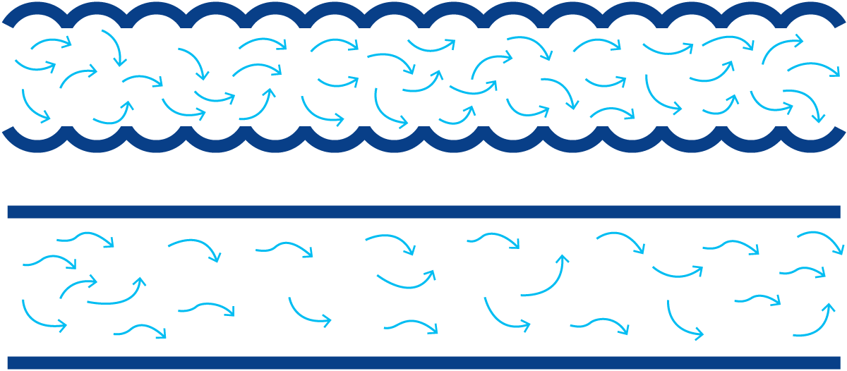
- Convection is a form of heat transfer that occurs when particles with a high heat content are mixed with cold particles and transfer their heat to the latter by conduction (Figure 7.1.4). Convection consequently involves mixing. If the teaspoon is rinsed with running cold water, heat is transferred from the spoon to the water, which is heated in the process. The heated water is replaced by cold water, which in turn absorbs heat from the spoon. Heat transfer by convection continues until the spoon and the running water have the same temperature.
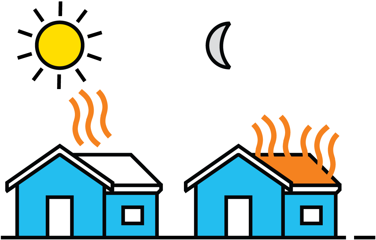
- Radiation is the emission of heat from a body that has accumulated thermal energy (Figure 7.1.5). The thermal energy is converted into radiant energy, emitted from the body and absorbed by other bodies that it strikes. Almost all substances emit radiant energy.
Heat transfer principles
All heat transfer in dairies takes place in the form of convection and conduction. Two principles are used: direct and indirect heating.
Direct heating
Direct heating means that the heating medium is mixed with the product. This technique is used to:
- Heat water, where steam is injected directly into the water and transfers heat to the water by both convection and conduction.
- Heat products, such as curd in the manufacture of certain types of cheese (by mixing hot water with the curd) and sterilised milk by the direct method (steam injection or infusion of milk into steam).
The direct method of heat transfer is efficient for rapid heating. It offers certain advantages which will be considered in Chapter 10 on long-life milk production. It does, however, involve mixing the product with the heating medium, and this necessitates certain steps in the subsequent process. It also makes strict demands on the quality of the heating medium.
Indirect heating
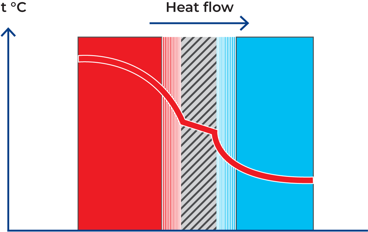
Indirect heat transfer is therefore the most commonly used method in dairies. In this method, a partition is placed between the product and the heating or cooling medium. Heat is then transferred from the medium through the partition into the product (Figure 7.1.6).
We assume that the heating medium is hot water, flowing on one side of the partition, and cold milk on the other. The partition is consequently heated on the heating-medium side and cooled on the product side. In a plate heat exchanger, the plate is the partition.
There is a boundary layer on each side of the partition. The velocity of the liquids is slowed down by friction to almost zero at the boundary layer in contact with the partition. The layer immediately outside the boundary layer is only slowed down by the liquid in the boundary layer and therefore has a low velocity. The velocity increases progressively and is highest at the centre of the channel.
Similarly, the temperature of the hot water is highest in the middle of the channel. The closer the water is to the partition, the more it is cooled by the cold milk on the other side. Heat is transferred, by convection and conduction, to the boundary layer. Transfer from the boundary layer through the wall to the boundary layer on the other side is almost entirely by conduction, while further transfer to the milk in the central zone of the channel is accomplished by both conduction and convection.
The heat exchanger
A heat exchanger is used to transfer heat by the indirect method. Several different types will be described later. It is possible to simplify heat transfer by representing the heat exchanger symbolically as two channels separated by a tubular partition.
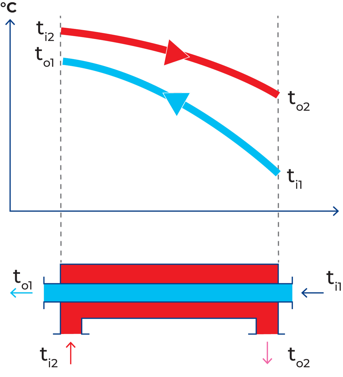
Hot water (red) flows through one channel and milk (blue) flows through the other. Heat is transferred through the partition. The hot water enters the channel at a temperature of ti2 and is cooled to a temperature of to2 at the outlet. Milk enters the heat exchanger at a temperature of ti1 and is heated by the hot water to an exit temperature of to1. The temperature changes during passage through the heat exchanger are shown by the curves in Figure 7.1.7.
Dimensioning data for a heat exchanger
The necessary size and configuration of a heat exchanger depend on many factors. The calculation is very intricate and is nowadays normally done with the aid of a computer.
The factors that must be considered are:
- Product flow rate
- Physical properties of the liquids
- Temperature programme
- Permitted pressure drops
- Heat exchanger design
- Cleanability requirements
- Required running times
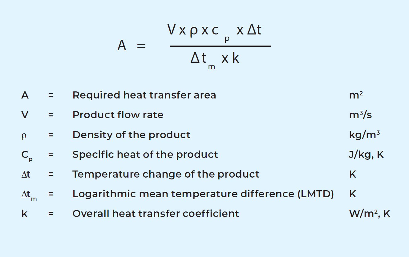
The general formula for calculating the required size (heat transfer area) of a heat exchanger is:
Product flow rate
The flow rate, V, is determined by the planned capacity of the dairy. The higher the flow rate, the larger the heat exchanger needed.
Example: If the product flow rate in a plant is to be increased from 10,000 to 20,000 l/h, the heat exchanger must be extended to twice the original size, provided the flow rates of the service media are also doubled, other factors being constant.
Physical properties of the liquids
The density figure, ρ, is determined by the product. The figure for specific heat, cp, is also determined by the product. The specific heat tells how much heat must be supplied to a substance in order to increase its temperature by 1 °C. Another important physical property is viscosity. This will be discussed in the section on the overall heat transfer coefficient below.
Temperature programme
The object of heat transfer is to heat or cool a given quantity of a product, such as milk, from a given inlet temperature to a given outlet temperature. This is accomplished in a heat exchanger with the help of a service medium, such as water. In the case of heating, milk is heated with hot water, the temperature of which drops correspondingly.
Several aspects of the temperature programme must be considered: the change of temperatures, the differential temperature between the liquids and the flow direction of the liquids.
Temperature change
Inlet and outlet temperatures of the product are determined by the preceding and subsequent process stages. The change in product temperature is marked Δt in the general formula above. It can be expressed as:
Δt1 = to1 – ti1. See also Figure 7.1.7.
The inlet temperature for the service medium is determined by processing conditions. The temperature for the outgoing service medium can be calculated by an energy balance calculation.
For a modern heat exchanger, the energy losses to the surrounding air can be neglected, as they are very small. Thus, the heat energy given off by the hot liquid is equal to the heat energy absorbed by the cold liquid, i.e. an energy balance. It can be expressed as the following formula:
Example: 20,000 l/h cheese milk (V1) is to be heated from 4 °C to 34 °C by 30,000 l/h hot water (V2) at 50 °C. Density (ρ) and specific heat (cp) for milk are about 1,020 kg/m3 and 3.95 kJ/kg, K and for water 990 kg/ m3 (at 50 °C) and 4.18 kJ/kg.
The temperature change for the hot water can then be calculated:
20,000 x 1,020 x 3.95 x (34 – 4) = 30,000 x 990 x 4.18 x Δt2
Δt2 = 19.5 °C. The hot water temperature will drop by 19.5 °C from 50 °C to 30.5 °C.
Logarithmic mean temperature difference (LMTD)
It has already been mentioned that there must be a difference in temperature between the two media for heat transfer to take place. The differential temperature is the driving force. The greater the temperature difference, the more heat is transferred and the smaller the heat exchanger needed. For sensitive products there are, however, limits to how great a difference can be used.
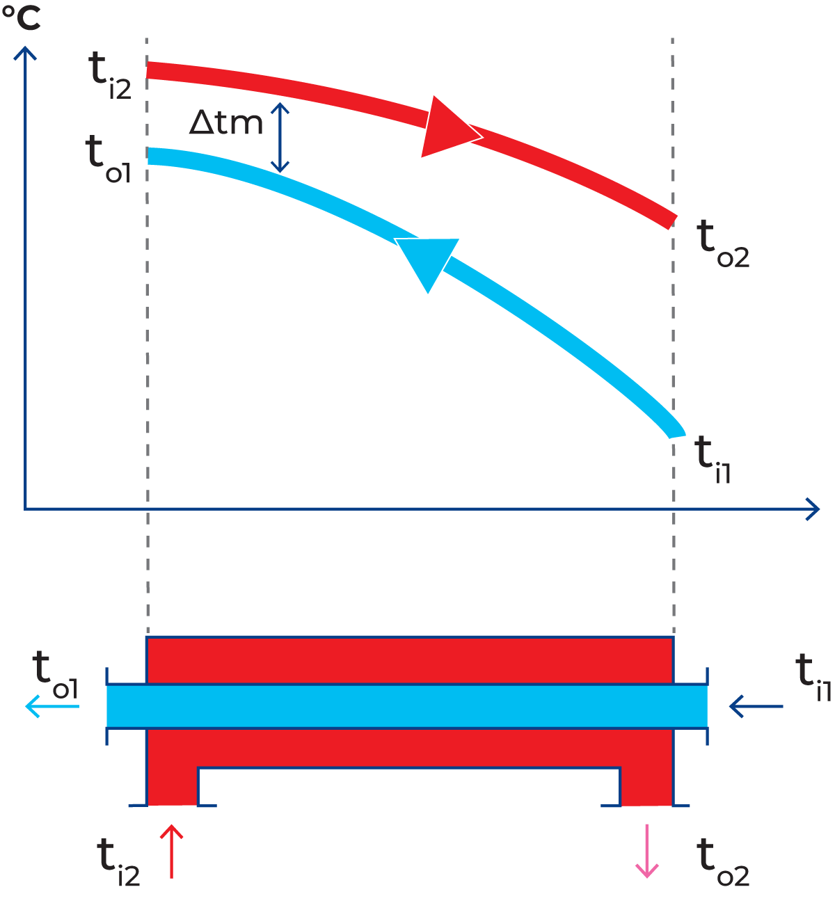
The differential temperature can vary through the heat exchanger. A mean value, LTMD, is used for calculation. It is called Δtm in the general formula above. It can be calculated by the following formula, using the denominations in Figure 7.1.8.
In the example with the cheese milk heater, the logarithmic mean difference temperature, Δtm, can be calculated as 20.8 °C. An important factor in determining the mean temperature differential is the direction of the flow in the heat exchanger. There are two main options: countercurrent or concurrent flow.
Countercurrent flow
The temperature difference between the two liquids is best utilised if they flow in opposite directions through the heat exchanger (Figure 7.1.8). The cold product then meets the cold heating medium at the inlet and a progressively warmer medium as it passes through the heat exchanger. During the passage, the product is gradually heated so that the temperature is always only a few degrees below that of the heating medium at the corresponding point. This type of arrangement is called countercurrent flow.
Concurrent flow
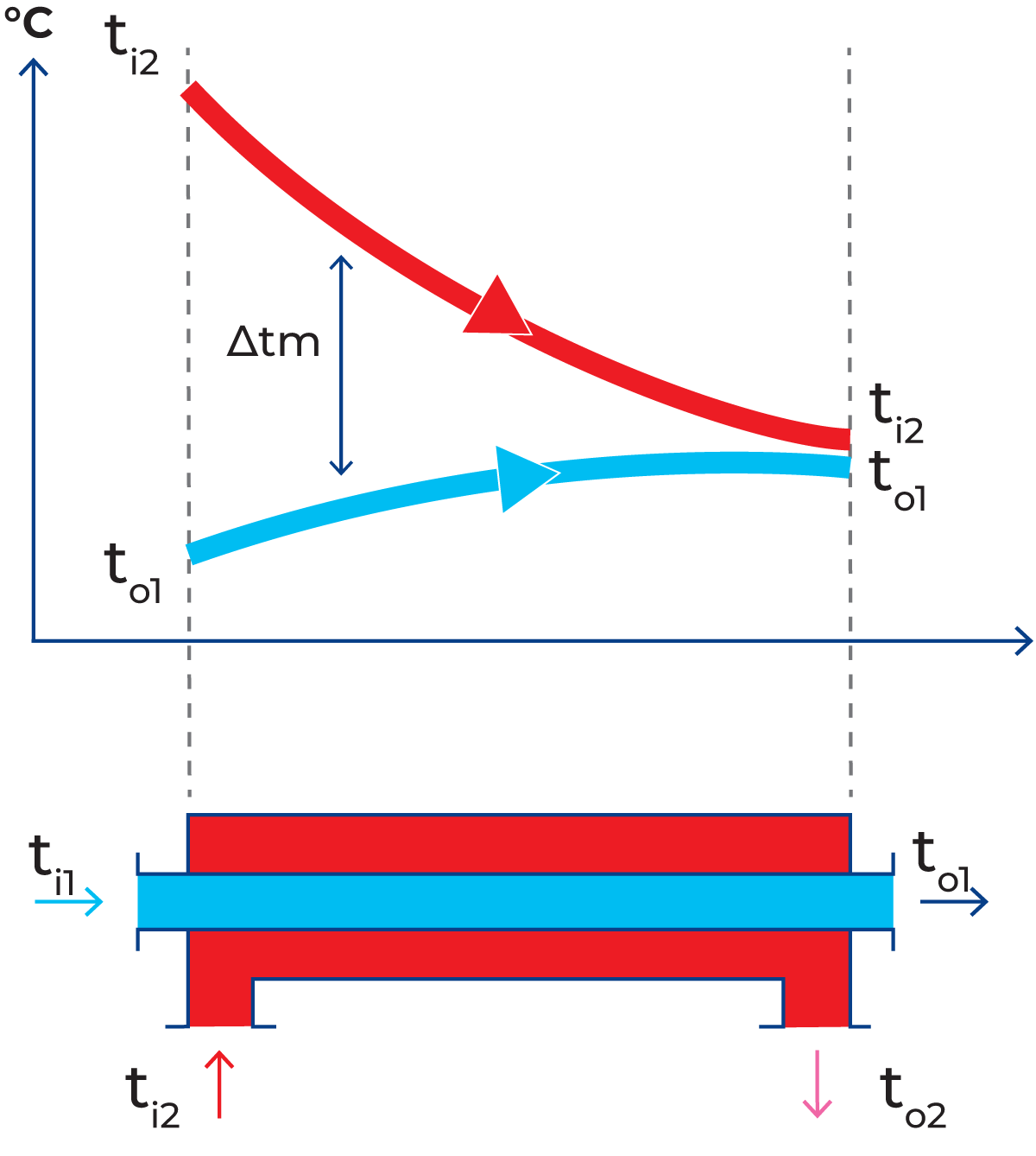
With the opposite arrangement, concurrent flow (Figure 7.1.9), both liquids enter the heat exchanger from the same end and flow in the same direction. In concurrent flow, it is impossible to heat the product to a temperature higher than that which would be obtained if the product and the heating medium were mixed. This limitation does not apply in countercurrent flow; the product can be heated to within two or three degrees of the inlet temperature of the heating medium.
Overall heat transfer coefficient
This factor, k, is a measure of how efficient the heat transfer is. It tells how much heat passes through 1 m2 of the partition per 1 °C of differential temperature. The same factor is used to calculate insulation for buildings, although in that case, the object is to make k as small as possible, whereas in a heat exchanger, it should be as high as possible.
This factor depends on:
- Permitted pressure drops for the liquids
- The viscosities of the liquids
- The shape and thickness of the partition
- The material of the partition
- Presence of fouling matter
Permitted pressure drops
In order to increase the value of k, and improve the heat transfer, it is possible to reduce the size of the channel through which the product flows. This reduces the distance over which heat must be transferred from the partition to the centre of the channel.
At the same time, however, the cross-section area of flow is reduced. This has two results:
a. The flow velocity through the channel increases, which in turn means
b. The flow becomes more turbulent.
When the flow becomes more turbulent the overall heat transfer coefficient is increased and thus a smaller heat exchanger area is required to transfer the heat.
Products that are sensitive to mechanical agitation (e.g. milk fat) may, however, be damaged by violent treatment. The pressure drop across the heat exchanger also rises, so the product pressure before the heat exchanger must be increased to force the product through the narrower channels. It may then be necessary to install a booster pump. In some countries, installation of a booster pump is specified in legal requirements, basically to secure a higher pressure on the product side, and thus to prevent leakage of unpasteurized product into pasteurized product.
Viscosity
The viscosities of the product and the service medium are important to the dimensioning of a heat exchanger. A liquid with high viscosity develops less turbulence when it flows through the heat exchanger compared to a product with lower viscosity. This means a larger heat exchanger is needed, assuming everything else remains constant. For instance, a larger heat exchanger is needed for cream than for milk, if capacities and temperature programs are identical. Special attention must be paid to products with non-Newtonian flow behaviour. For these products, the apparent viscosity depends not only on the temperature but also on the shear rate. A product that seems rather thick in a tank may flow much more readily when it is pumped through pipes or a heat exchanger. The flow behaviour of such products must be measured with special instruments so that correct calculations can be made. (See also Chapter 3, Rheology.)
Shape and thickness of the partition
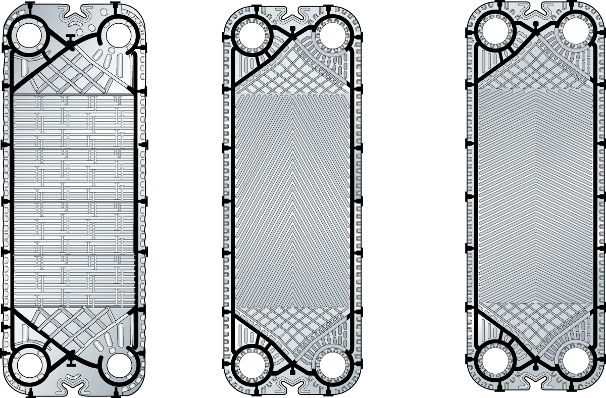
The partition in plate heat exchangers is often corrugated to create a more turbulent flow, which results in better heat transfer. Figure 7.1.10 shows three different designs.
Plates with different corrugations according to A) and B) in the figure, have different thermal properties and pressure drops. With these two plate types, three different channels can be formed. This gives the possibility to optimise the heat transfer/pressure drop relation for a certain duty.
Figure C) shows a plate with a completely different corrugation. The number of contact points is reduced to make it possible to run liquids with particles or fibres of limited size.
The thickness is also important. The thinner the partition, the better the heat transfer. But this must be balanced against the need for the partition to be strong enough to withstand the pressure of the liquids. Modern plates are designed with metal-to-metal contact points that provide effective pressure resistance even for thin plates.
The heat transfer in tubular heat exchangers can be improved by corrugation of the inner tubes (Figure 7.1.11). This will however also give a higher pressure drop. Smooth or corrugated tubes are chosen in order to optimise the heat transfer/pressure drop relation.
Material of the partition
For food processing, the normal material is stainless steel, which has fairly good heat transfer characteristics.
Presence of fouling matter
Most dairy products are sensitive to heating, which must therefore be done very carefully to avoid changes in the products. Proteins will coagulate and encrust the inside of a hot saucepan if it is used to heat milk. The same thing happens in heat exchangers if the heat transfer surface is too hot.
The differential temperature between the heating medium and the product should therefore be as small as possible, normally 2 – 3 °C above the pasteurization temperature. If the surface is too hot, in relation to the product, there is a risk that proteins in the milk will coagulate and be deposited in a thin layer on the partitions. Heat must then also be transferred through this layer, which will cause the value of the overall heat transfer coefficient k to drop.
The differential temperature between the heating medium and product will then no longer be sufficient to transfer the same amount of heat as before, and the temperature at the product outlet will drop. This can be compensated for by increasing the temperature of the heating medium, but this also raises the temperature of the heat transfer surface so that more protein coagulates on the surface, the thickness of the crust increases, and the value of k drops still more.
The value of k is also affected by an increase or decrease in the flow rate through the heat exchanger, as this affects the flow characteristics. Increasing the flow rate makes the flow more turbulent and increases the value of k. Throttling the flow makes it less turbulent and reduces the value of k. It is therefore normally desirable to avoid variations in the flow rate through a heat exchanger. However, due to economic reasons, it might be necessary to accept some variations in certain types of production.
Example: In the previously considered case of the cheese milk heater, the heat transfer coefficient can be assumed to be about 5,000 W/m2, K, if a plate heat exchanger made of thin stainless steel is used and the plates are not heavily fouled.
The other factors in the formula shown on page 101 are:
Flow rate, l/h = 20,000
Density, kg/m3 = 1,020
Specific heat, kJ/kg, K = 3.95
Temperature change, °C = 30
Temperature difference, °C = 20.8
Heat transfer coefficient, W /m2, K = 5,000
The necessary heat transfer surface can be calculated as:
This is to be considered as a theoretical value. In actual practice, the sensitive nature of the product and the process demands must also be considered. Two such factors, not included in the formula, are the requirements for cleanability and running time.
Cleanability requirement
A heat exchanger in a dairy must be cleaned at the end of a production cycle. This is done by circulating detergents the same way as the milk. The cleaning process is described separately in Chapter 21.
To achieve efficient cleaning, the heat exchanger must be designed not only to meet the required temperature programme but also with cleaning in mind.
If some passages in the heat exchanger are very wide, i.e. have several parallel channels, the turbulence during cleaning may not be enough to remove fouling deposits effectively. On the other hand, if some passages are very narrow, i.e. few parallel channels, the turbulence may be so high that the pressure drop will be very significant. Such a high pressure drop may reduce the flow velocity of the cleaning solution, thereby reducing its effectiveness. A heat exchanger must thus be designed to allow effective cleaning.
When liquids with particles or fibres have been processed through a heat exchanger, back flush is normally needed during cleaning. Back flush means that the flow is reversed during some phases of the cleaning programme.
Running time requirement
Some fouling always occurs when milk products are heated to a temperature above 65 °C. This means that there will always be a limited running time before the pasteurizer must be stopped for cleaning.
The length of the running time is difficult, not to say impossible, to predict, as it is determined by the amount of fouling formed.
The rate of buildup of fouling depends on many factors such as:
- Temperature difference between product and heating medium
- Milk quality
- Air content of the product
- Pressure conditions in the heating section
It is especially important to keep the air content as low as possible. Excess air in the product will greatly contribute to increased fouling. Under certain conditions, the running time may also be limited by the growth of microorganisms in the downstream part of the regenerative section of a plate heat exchanger. This is however rare; when it occurs, it is usually related to the pre-treatment of the milk.
All this together makes it important to allow for cleaning at regular intervals when making production plans for pasteurizers.
Regeneration
The method of using the heat of a hot liquid, such as pasteurized milk, to pre-heat cold incoming milk is called regeneration. The cold milk also serves to cool the hot, thus economising on water and energy. Regeneration efficiencies of up to 95% can be achieved in efficient, modern pasteurizers.
We can take the simplest operating profile – heat treatment of raw milk – as an example. Using the formula:
Holding
Correct heat treatment requires that the milk is held for a specified time at pasteurization temperature. This is done in an external holding cell.
A holding cell usually consists of a pipe arranged in a spiral or zig-zag pattern and is often covered by a metal shroud to prevent people from being burned if they touch it. The shroud will also reduce the heat losses to the surrounding air. The length of the pipe and flow rate are calculated so that the time in the holding cell is equal to the required holding time.
Accurate control of the flow rate is essential because the holding equipment is dimensioned for a specified holding time at a given flow rate. The holding time changes in inverse proportion to the flow rate in the holding cell.
Holding sections, which were built into the plate heat exchanger were previously used, but nowadays external holding cells are used almost exclusively.
Calculation of holding time
The appropriate tube length for the required holding time can be calculated when the hourly capacity and the inner diameter of the holding tube are known. As the velocity profile in the holding tube is not uniform, some milk molecules will move faster than the average. To ensure that even the fastest molecule is sufficiently pasteurized, an efficiency factor must be used. This factor depends on the design of the holding tube but is often in the range of 0.8 – 0.9 if the flow is turbulent. For more viscous fluids, the flow might be laminar and then the efficiency factor is lower.
Data required for calculation:
Q = flow rate at pasteurization, l/h
HT = holding time in seconds
L = length of holding tube in dm, corresponding to Q and HT
D = inner diameter of holding tube in dm, to be known or adapted to the other pipework
V = volume of milk in l or dm3 corresponding to Q and HT
η = efficiency factor
Example: A holding time (HT) of 15 sec is required in a pasteurizer with a capacity (Q) of 10,000 l/h. The inner diameter (D) of the pipe to be used is 48.5 mm = 0.485 dm. Calculate the length (L) of the holding tube with an efficiency factor of 0.85.
The length of the holding tube should be about 26.5 m.
Different types of heat exchangers
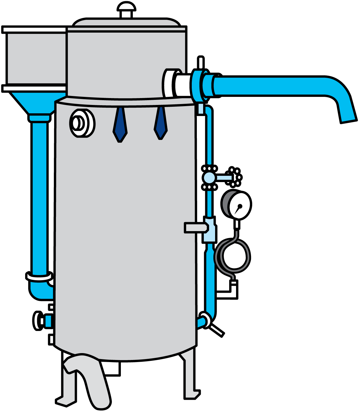
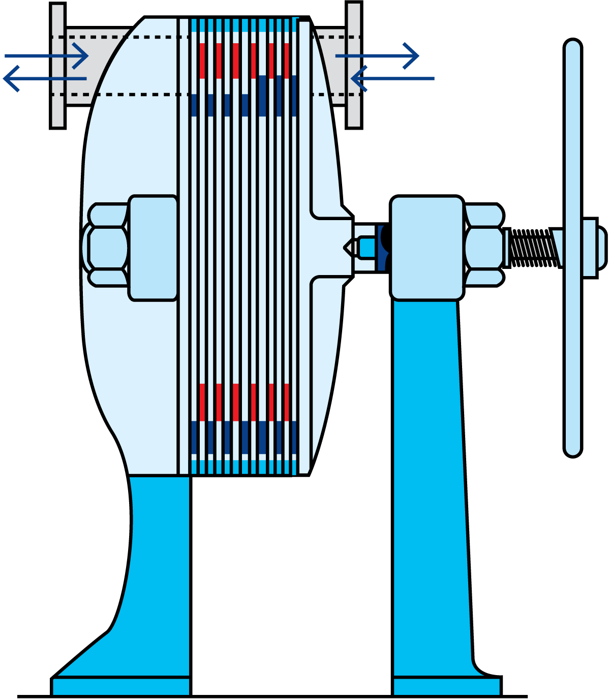
The most widely used type of equipment at the end of the 19th century was the heater, one type of which is shown in Figure 7.1.14. Despite its many shortcomings, this heat exchanger model was still in use in some dairies even in the 1950s.
In 1878 a German, Albert Dracke, was granted a patent on an apparatus in which one liquid could cool another by each flowing in a layer on opposite sides of a series of plates. It is not known whether any such patents, one of which covers the heat exchanger shown in Figure 7.1.15, ever left the drawing board. However, at the beginning of the 1920s, the old German ideas were reappraised, and a regenerative heat exchanger, based on these concepts, was launched. Since then, plate heat exchangers have assumed a predominant role for heating and cooling purposes in the dairy industry.
The following four types of heat exchangers are the most widely used nowadays:
- Plate heat exchanger
- Tubular heat exchanger
- Scraped-surface heat exchanger
- Coiled heat exchanger
Plate heat exchangers
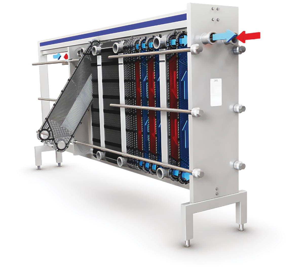
Most heat treatment of dairy products is carried out in plate heat exchangers. The plate heat exchanger (often abbreviated PHE) consists of a pack of stainless steel plates clamped in a frame.
The frame may contain several separate plate packs – or sections – in which different stages of treatment, such as pre-heating, final heating and cooling take place. The heating medium is hot water, and the cooling medium is cold water, ice water, or propylene glycol, depending on the required product outlet temperature.
The plates are corrugated in a pattern designed for optimum heat transfer. The plate pack is compressed in the frame. Supporting points on the corrugations hold the plates apart so that thin channels are formed between them.
The liquids enter and leave the channels through holes in the corners of the plates. Varying patterns of open and blind holes route the liquids from one channel to the next. Gaskets around the edges of the plates and holes form the boundaries of the channels and prevent external leakage and internal mixing.
Flow patterns
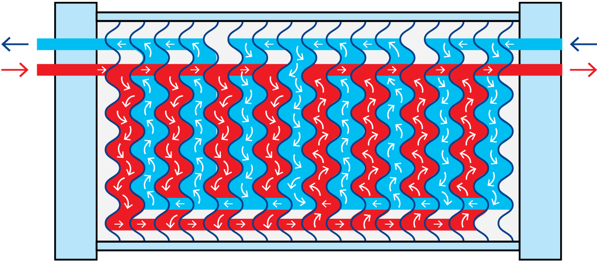
The product is introduced through a corner hole into the first channel of the section and flows vertically through the channel. It leaves at the other end through a separately gasketed corner passage. The arrangement of the corner passages is such that the product flows through alternate channels in the plate pack.
The service (heating or cooling) medium is introduced at the other end of the section and passes, in the same way, through alternate plate channels. Each product channel consequently has service medium channels on both sides.
For efficient heat transfer, the channels between the plates should be as narrow as possible, but both flow velocity and pressure drop will be high if a large volume of product must pass through these narrow channels. Neither of these effects is desirable and, to eliminate them, the passage of the product through the heat exchanger may be divided into a number of parallel flows.
In Figure 7.1.17 the blue product flow is divided into two parallel flows, which change direction four times in the section. The channels for the red heating medium are divided into four parallel flows, which change direction twice.
This combination is written as 4 x 2 / 2 x 4, i.e. the number of passes, the number of parallel flows for the blue product, the number of passes, and the number of parallel flows for the red service medium. This is called the grouping of the plates.
Tubular heat exchangers
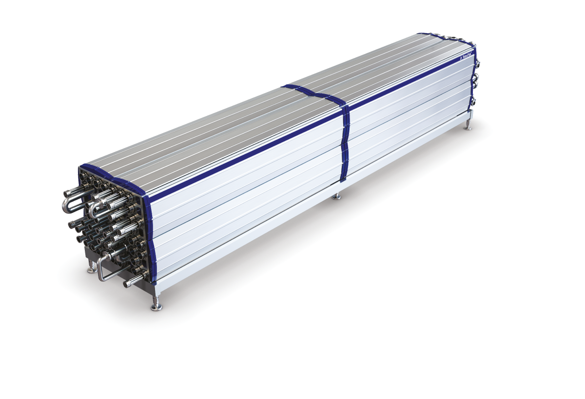
Tubular heat exchangers (THE) are in some cases used for pasteurization and UHT treatment of dairy products. The tubular heat exchanger (Figure 7.1.18), unlike plate heat exchangers, has no contact points in the product channel and can thus handle products with particles up to a certain size. The maximum particle size depends on the diameter of the tube. The tubular heat exchanger can also run longer between cleanings than the plate heat exchanger in UHT treatment.
Compared to a plate heat exchanger, a higher flow velocity is needed to create efficient heat transfer in a tubular heat exchanger.
Tubular heat exchangers are available in two fundamentally different types; multi/monotube and concentric tube.
Multi/mono tube
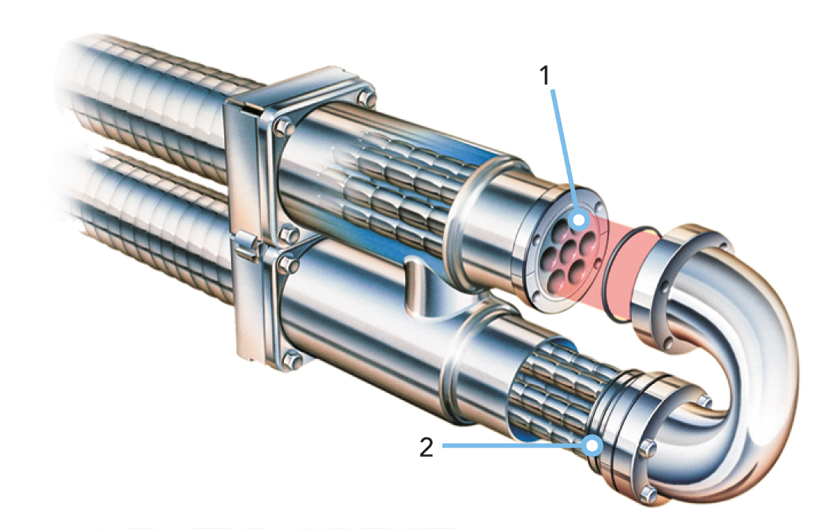
The multitube tubular heat exchanger operates on the classic shell and tube principle, with the product flowing through a group of parallel tubes and the service medium between and around the tubes. Turbulence for efficient heat transfer is created by helical corrugations on the tubes and shell.
The heat transfer surface consists of a bundle of straight corrugated or smooth tubes (1) welded into tube plates at both ends (Figures 7.1.19 and 7.1.20). The tube plates are in turn sealed against the outer shell by a double O-ring construction (2) (floating design). This design allows the product tubes to be removed from the shell by unscrewing the end bolts. This makes the unit strippable for inspection.
The floating design absorbs thermal expansion and the product tube bundles in the shell can be changed, allowing different combinations to be used for different applications.
Direct product-to-product heat recovery can be utilised in a multitube with a special design. This is because the tube inserts can be taken out for inspection also on the shell side.
The monotube is a version with only one inner tube, which will permit particles with a diameter of up to 50 mm to pass through.
Multi/monotubes are well suited for processes operating at very high pressures and high temperatures.
Concentric tube
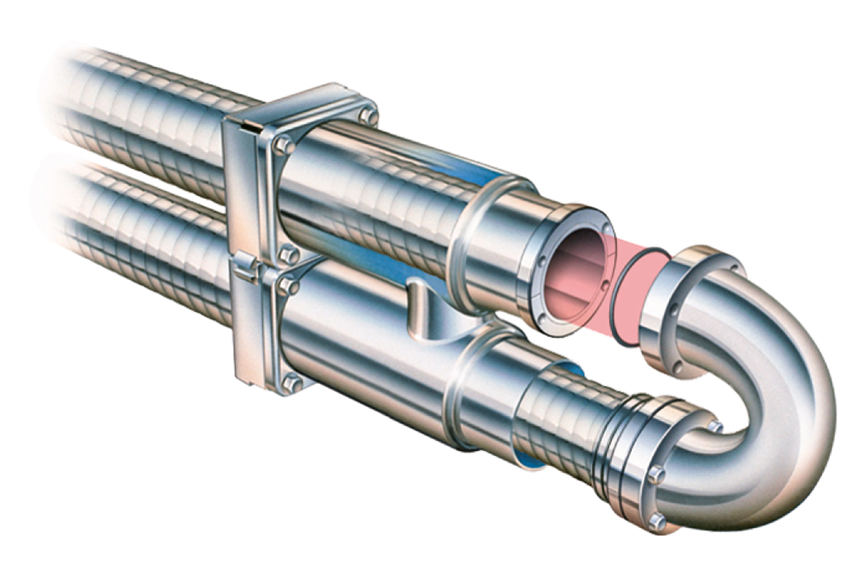
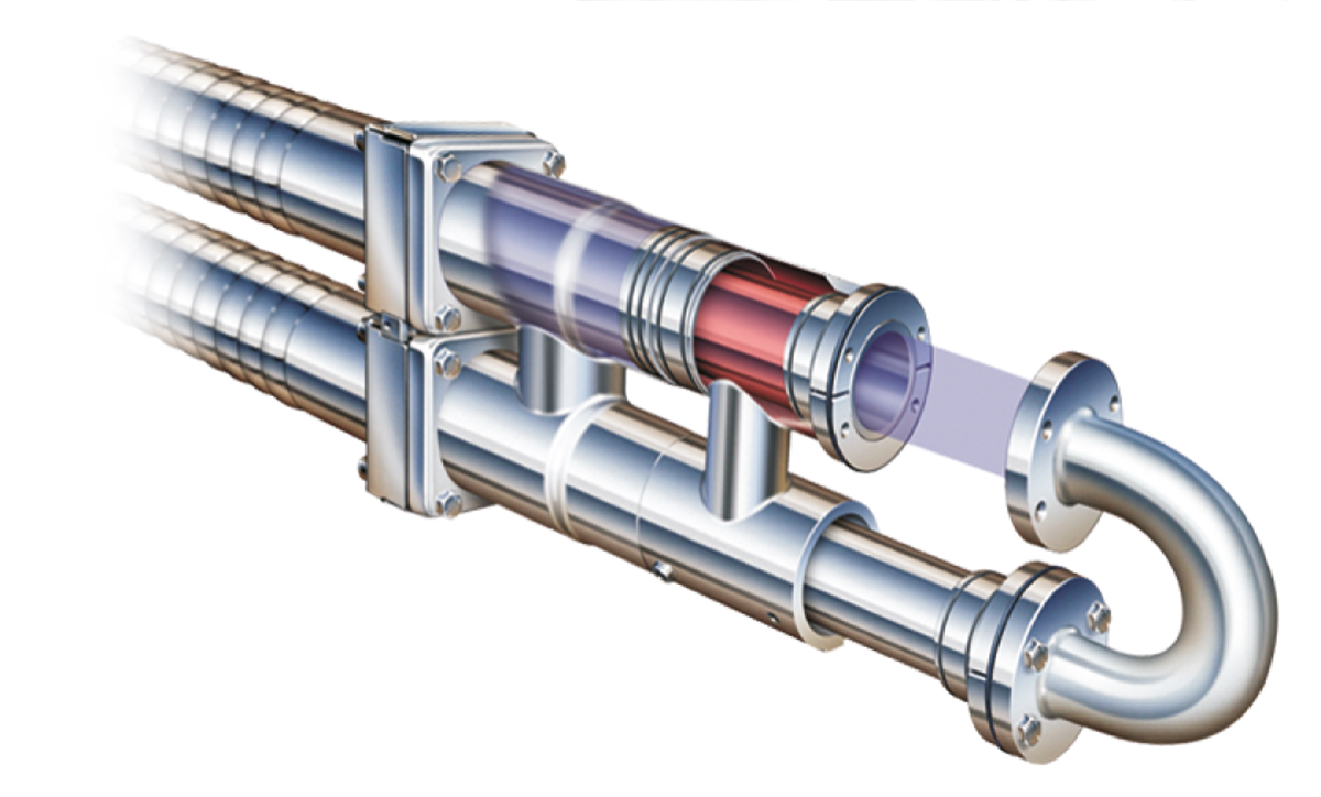
The heat exchanger surface of a concentric tubular heat exchanger, shown in Figure 7.1.21, consists of straight tubes of different diameters concentrically located. This design gives efficient heating or cooling as there is heating/ cooling media on both sides of the annular product channel. The product channel is available with different depths to meet the requirements for products with particles. The concentric tube is designed with floating tubes to absorb thermal expansion and to make it possible to inspect both product and media channels.
A concentric tube is especially well suited for high-viscous fluids with strong non-Newtonian flow behaviour.
Scraped-surface heat exchanger
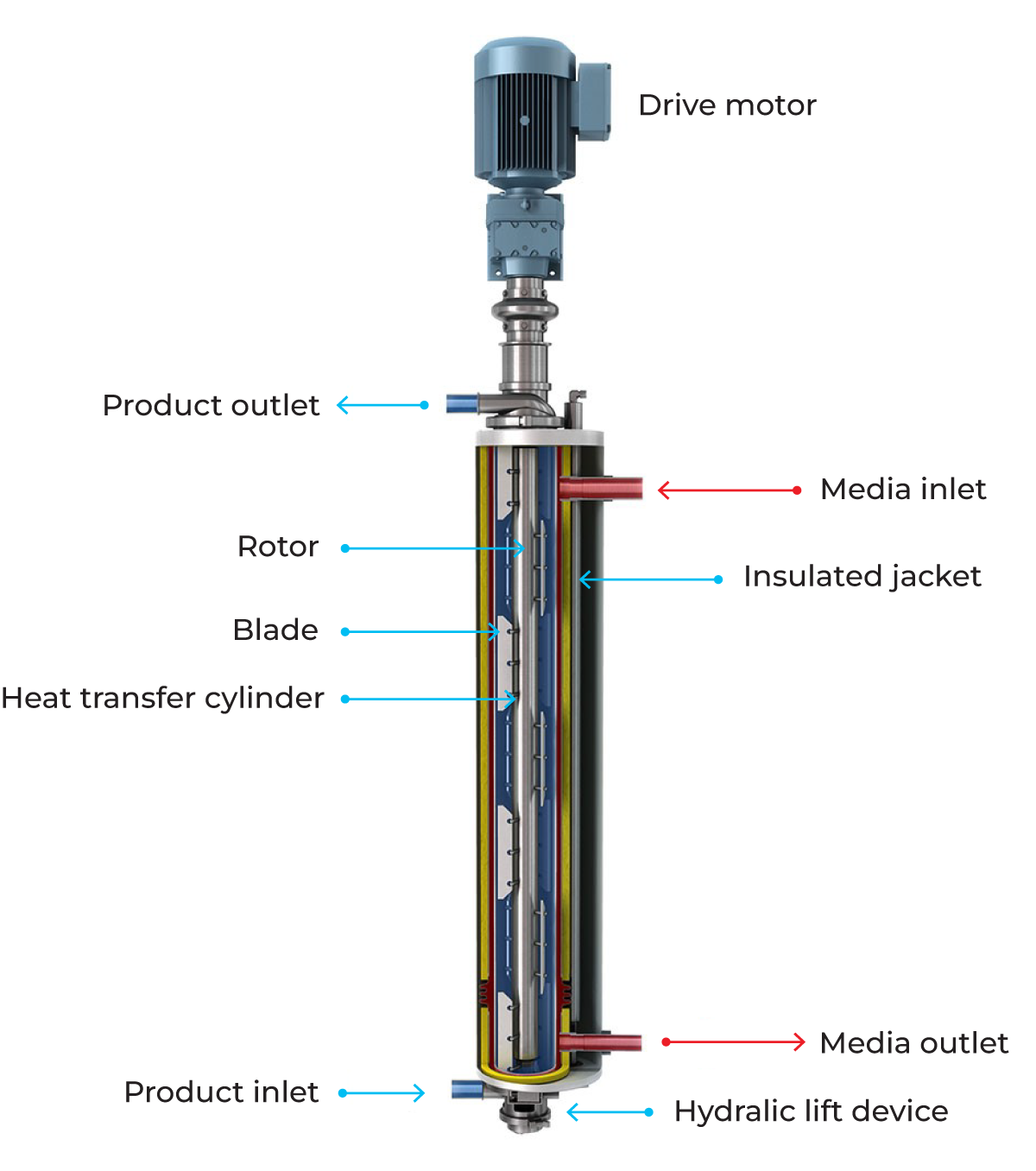
The scraped-surface heat exchanger (Figure 7.1.22), is designed for the heating and cooling of viscous, sticky and lumpy products and the crystallisation of products. All products that can be pumped can also be treated.
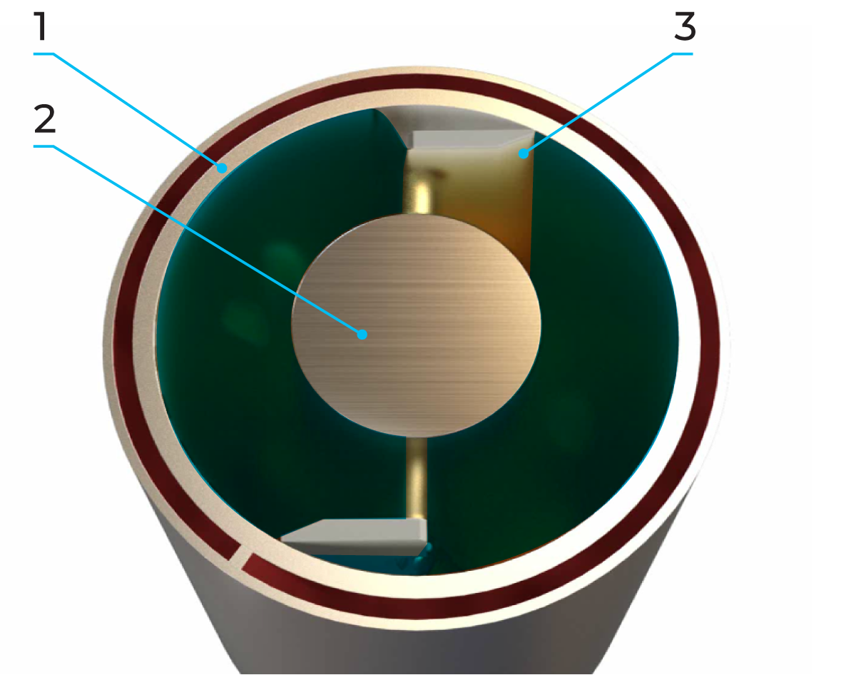
A scraped surface heat exchanger consists of a cylinder (1) through which the product is pumped in countercurrent flow to the service medium in the surrounding jacket. Exchangeable rotors (2) of various diameters, and varying pin/blade (3) configurations allow adaptation to different applications. Smaller diameter rotors allow larger particles to pass through the cylinder, while larger diameter rotors result in shorter residence time and improved thermal performance.
The product enters the vertical cylinder through the lower port and continuously flows upwards through the cylinder. At process start-up, all the air is completely purged ahead of the product, allowing complete and uniform product coverage of the heating or cooling surface.
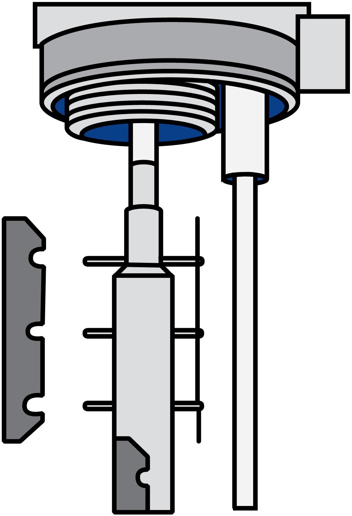
The rotating blades continually remove the product from the cylinder wall (Figure 7.1.23), to ensure uniform heat transfer to the product. In addition, the surface is kept free from deposits.
The product exits the cylinder via the upper port. Product flow and rotor speed are varied to suit the properties of the product flowing through the cylinder.
At shut-down, thanks to the vertical design, the product can be displaced by water with minimum intermixing, which helps assure product recovery at the end of every run. Following this, complete drainage facilitates CIP and product changeover.
As mentioned above, the rotor and blades are exchangeable, an operation that is possible due to the automatic hydraulic lift that facilitates raising and lowering the rotor/blade assembly, (Figure 7.1.24).
Typical products treated in the scraped-surface heat exchanger are jams, sweets, dressings, chocolate and peanut butter. It is also used for fats and oils for crystallisation of margarine and shortenings, etc.
The scraped-surface heat exchanger is also available in versions designed for aseptic processing.
Two or more vertical-type scraped-surface heat exchangers can be linked in series or parallel to give a greater heat transfer surface depending on the processing capacity required.
Coiled heat exchanger
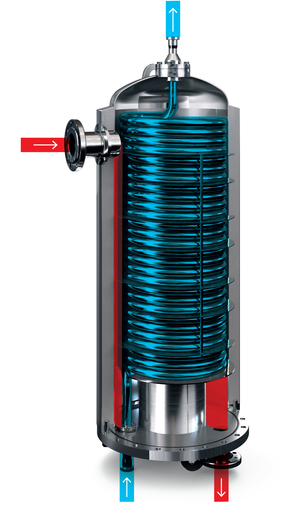
In a coiled tubular heat exchanger, the product flows through a coil-shaped tube and media flows around the product tube to heat or cool the product. A unique feature of the coiled design is that it creates a secondary flow pattern at high velocity, which significantly increases the heat transfer efficiency. This secondary flow pattern is called the Dean effect.
With laminar flow in straight tubes, the heat transfer to the fluid is maintained purely by heat conduction in the fluid. Therefore, the heat transfer efficiency is lower than in turbulent flow where intensive mixing takes place thus greatly increasing the heat transfer.
In coiled tubes, the Dean vortices will act as "internal mixers" transporting fluid elements from the tube wall into the tube centre and vice versa. The mixing procedure will greatly reduce the time needed for the desired heat transfer to take place thus reducing the length and the necessary heating surface of the heat exchanger. In addition, the residence time and hence the product volumes will be decreased.
The magnitude of the heat transfer enhancement is dependent on the design of the coil, the velocity of the fluid and the physical properties of the fluid. The enhancement is based on the Dean number, which has to exceed 100 to give any significant effect. High Dean numbers are usually reached by high product velocities in combination with a tightly coiled tube.
The coiled mono-tube unit— between 30 and 100 metres long — has only one inlet and one outlet connection. This enables gentle mechanical treatment and ensures excellent particle integrity for particles of up to 25 mm in diameter. The unit is designed for high hygiene and easy maintenance with floating ends through the top and bottom flanges.
The coiled product tube is placed in a vertical chamber where the heating or cooling media flows. The bottom and top product tube connections are sealed by O-rings to create a system that allows movement between the product tube and the media shell. This design absorbs the effects of thermal expansion and prevents the tube from cracking. The unit is supplied with insulation to minimise heat losses and ensure operator safety. The heat exchanger dimension is selected based on each specific application – the number of units depends on the desired capacity and required heat transfer area.
Typical products treated in the coiled heat exchanger are dairy-based dessert puddings, tomato paste, ketchup, fruit purées and products with particles.
De = Re√(Dt/Dc)
Dt tube diameter m
Dc coil diameter m
Re Reynolds No. = Dtvρ/μ -
v fluid velocity m/s
ρ fluid density kg/m3
μ fluid dynamic viscosity Pas
