Service systems
Prerequisites for dairy processing
Several service installations must be supplied for dairy operations. Among these are water, heat in the form of steam and hot water, refrigeration, compressed air and electricity.
Water supply equipment
Water in nature moves in a continuous cycle (Figure 8.3.1). Heated by the sun, it evaporates from the surface of the oceans, seas and lakes. The water is suspended in the air and carried by the wind over land where it cools, condenses and falls as rain, hail or snow. Some of it, the surface water, runs from the ground directly to lakes and rivers and returns to the sea. The remainder soaks through the top layers of the soil and becomes groundwater.
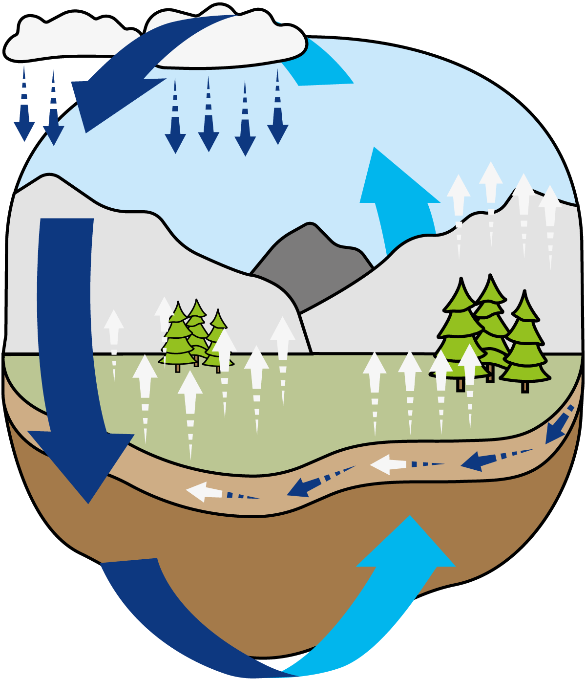
Fig. 8.3.1 The water cycle in nature.
Water is a solvent for many substances, so pure water does not exist in nature. Gases such as sulphur dioxide dissolve in water while still in the air, causing “acid rain” which is a major problem in industrialised countries. Water also begins to dissolve various substances as soon as it reaches the ground. Surface water picks up organic matter, insecticides, chemicals from industrial effluents, etc. from the topsoil, as well as bacteria and other microorganisms. As the water filters through the various layers of soil, much of the organic matter is removed, together with a proportion of the organisms and chemicals. At the same time, several naturally occurring salts are added, so that groundwater is often fairly rich in salts of various kinds. These are present as ions of, e.g. sodium, potassium, magnesium, calcium, chloride, carbonate, nitrate and sulphate.
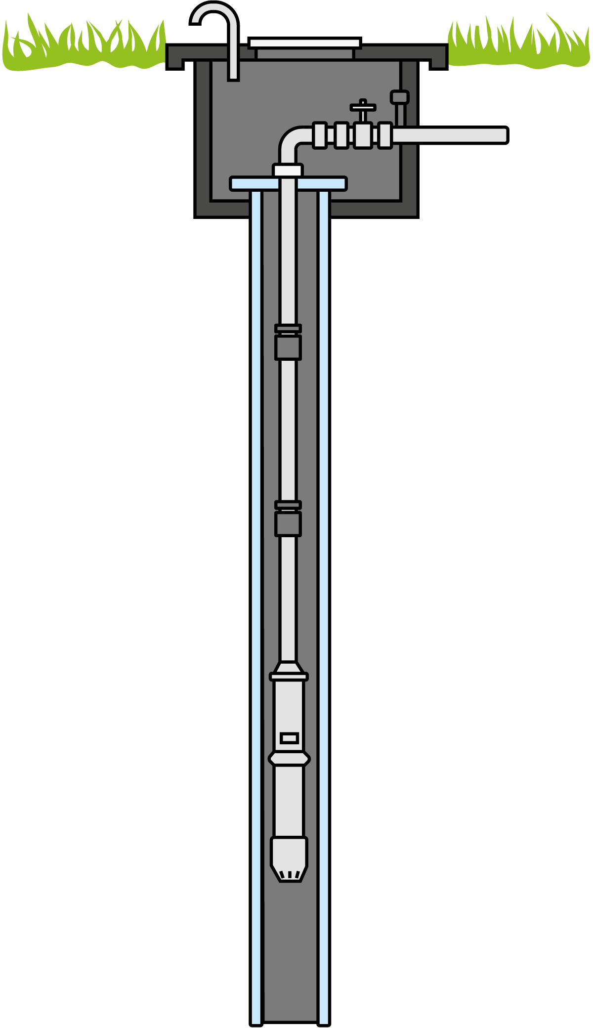
Fig. 8.3.2 Pipe well with submersible pump.
Groundwater is therefore the least polluted supply, but the composition varies from place to place according to local wastewater discharge, soil conditions and many other factors. Dissolved and suspended substances in the water supply can cause problems in dairies. The incoming water must therefore be treated so that harmful substances can be reduced in concentration, neutralised, or removed altogether.
Most countries have strict legislation regarding the content of microorganisms and toxic compounds in water. Analytical procedures, methods of sampling and the intervals between sampling are precisely specified. The diseases that can be transmitted by water are chiefly intestinal, so testing for pathogenic types of bacteria often concentrates on E. coli. Faecal pollution is indicated if E. coli are present in significant quantities.
The dairy industry consumes large quantities of water for various purposes, such as pre-treatment of dairy products, rinsing of equipment, cooling and cleaning. The quantity used varies from dairy to dairy according to cleaning methods, etc. and whether water is consumed in production, e.g. for recombining milk from powder or juice production.
The dairy water supply often comes from the municipal waterworks. This water is taken from a river or a lake and is then treated so that it meets the requirements for drinking water. The water authority delivers the water to the dairy at the pressure and in the quantity required. The intake is measured and recorded. The price paid by the dairy is then calculated per unit of volume and includes an additional levy for municipal wastewater treatment.
Many dairies have their own wells. A simple well shaft is dug where the groundwater is close to the surface. A long tube is driven into the ground if the water is deeper down, as shown in Figure 8.3.2. The water is brought up via a pump, often submersible, and stored in a reservoir – usually at ground level but sometimes at a higher level (a water tower). From here, it is delivered by pumping or gravity to the various points of consumption in the dairy.
Water treatment
Water has many applications in a dairy and the quality requirements vary with the application. With present-day techniques of filtration, softening, ion exchange, sterilisation, total desalination and reverse osmosis, it is possible to obtain water of a very high quality, but the cost is also high. It is therefore important that the quality demands for different applications are carefully defined so that the water can be treated accordingly.
Water used in the manufacture of dairy products must be of the highest quality, exceeding the requirements for acceptable drinking water. It should consequently be completely clear, free from smell, colour and taste, soft and virtually sterile. Softening (reducing the calcium and magnesium content) and dechlorination (removal of chlorine disinfectant by filtration through active carbon) are therefore necessary.
All water used for steam generation and feed water for boilers should also be softened to prevent scale from forming on the heating surfaces. Boiler scale is undesirable in terms of both safety and economy.
Piping system design
Water is distributed from the intake to wherever it is needed in the dairy. The water flows through a piping system similar to that used for the product. Stainless steel is used for pipes transporting water that will be in contact with the food product. For service water not in contact with the product, lower quality piping is also suitable. The system includes shut-off valves, pressure gauges and routing valves. Strainers and sometimes pressure-reducing valves are incorporated to maintain the required pressure in the system.
Many dairy applications make special demands on the water supply. Large quantities of water are often needed over a relatively short period at a sustained high pressure. Short but intensive periods of consumption may occur at several outlet points simultaneously. The system and the pressure must therefore be dimensioned to suit these instantaneous load conditions.
For example, a dairy might increase its output without increasing the water supply capacity to match. If this happens, and several instantaneous loads occur simultaneously, the supply pressure will drop to a critically low level for the proper functioning of certain equipment. A pressure tank can be used to prevent this. The pressure tank acts as an accumulator. A typical volume of a water tank is 1 – 3 m3. Water is held in the tank at a pressure determined by an air cushion. On demand, the pressure tank supplies the equipment with the required amount of water at the required pressure. When the instantaneous demand has been met, the tank accumulates more water in preparation for the next withdrawal. Figure 8.3.3 shows this type of pressure tank. During periods of zero demand, the tank is filled with water to the preset pressure. The pressure switch (4) shuts off the power supply to the pump (6). As soon as water is drawn from the tank, the resulting drop in pressure is sensed by the pressure switch which, via a contactor, starts the pump and water is pumped into the tank. When the withdrawal operation is over, the water level rises in the tank until the preset pressure is reached again. The pressure switch then stops the pump, and the pressure tank is ready to meet the next instantaneous demand.
The same function, as described above, can be achieved by using frequency-controlled pumps and a small pressure tank.
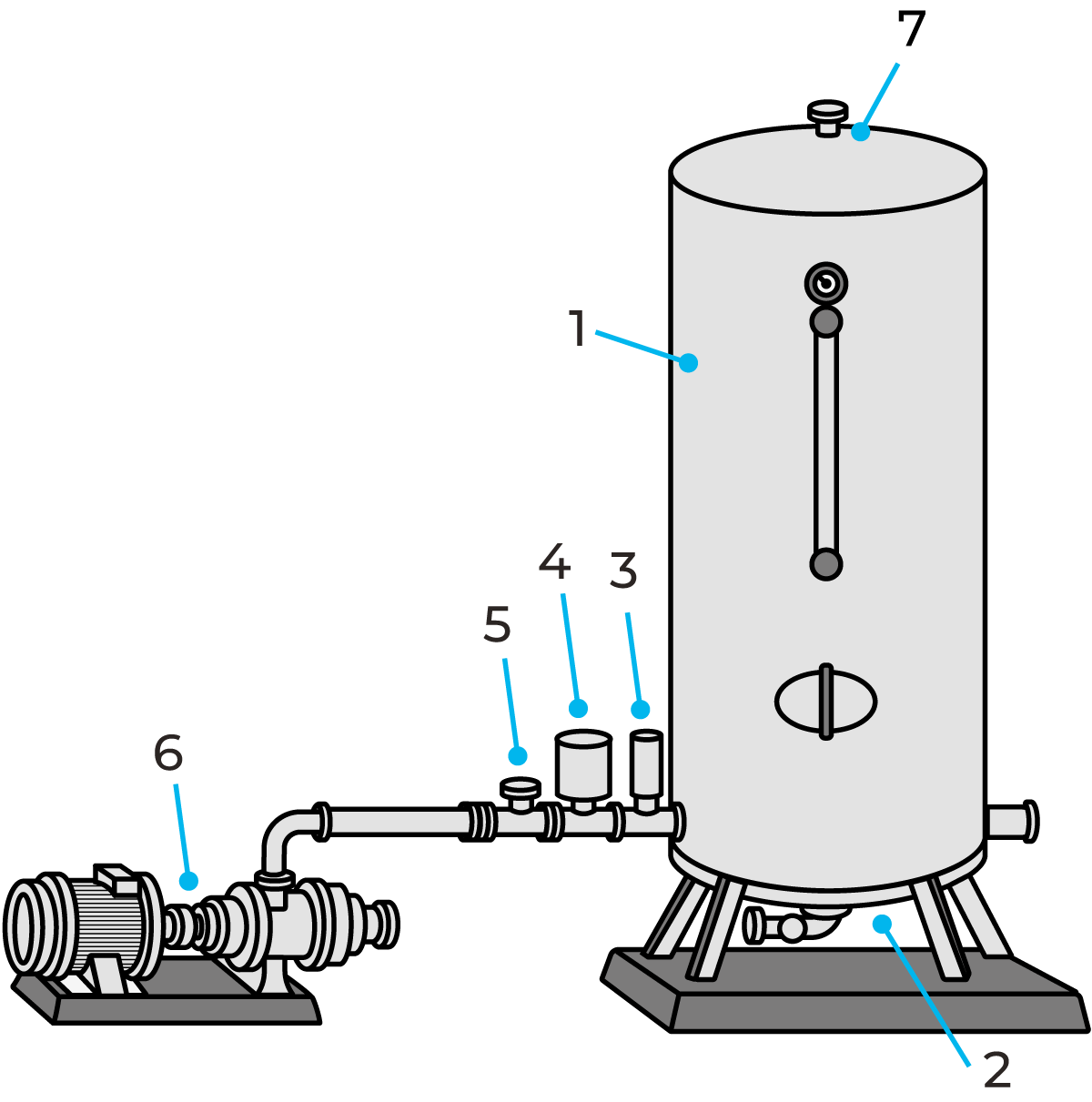
Fig. 8.3.3 Water pressure tank
- Tank
- Drain valve
- Safety valve
- Pressure switch
- Check valve
- Liquid-ring pump
- Vent valve
- Pressure gauge
- Level glass
Heat production
The operation of a dairy requires large quantities of thermal energy to heat various products, detergent solutions, etc. Heat is usually transferred to the product in heat exchangers by a thermal conductor known as the heating medium. This medium is generated in a heating plant and is distributed through a piping system to the various points of consumption (e.g. the heat exchanger in the hot water unit of a pasteuriser). Here, heat is transferred to the product to be heated. The heating medium then flows back to the heating plant, where it is reheated before returning to the points of consumption.
Steam at a temperature of 140 – 150 °C is frequently used as a heating medium. Systems using hot water have been installed in dairies which have been built in recent years. Most equipment requires a water temperature of around 100 °C for heating. UHT plants, however, require steam at higher temperatures. A water heating systems operating above 100°C must be pressurised to avoid boiling. The pressure in the system must be above atmospheric pressure so that the water cannot boil. The installation cost of a hot water system is slightly lower than that of a steam system. The system is also easier to regulate, and the operation is simpler. The disadvantage is that heat transfer in a hot water system is lower than in a steam system. The mass flow in a hot water system must be higher to account of the energy density compared to a steam system. Also, steam systems provide additional energy from the condensation of steam.
Steam production
Generation of the heating medium takes place in steam boilers which are sometimes located in the heating plant. The boiler is usually fuelled with oil, coal or gas. Thermal energy is released by the burning fuel and absorbed by the heating medium. The efficiency of the boiler is in the range of 80 – 92%, and heat losses in the piping system often amount to about 15%. Consequently, only between 65 and 77% of the total thermal energy of the fuel can be utilised in production. From the point of view of operating costs, it is most important that the efficiency of the boiler does not drop below the minimum level, and for this reason, boiler efficiency is very closely checked in the dairy.
The steam temperature in the steam system described below must be between 140 and 150 °C. In the case of saturated steam, this is equivalent to a gauge pressure of 270 – 385 kPa (2.7 – 3.8 bar). The boilers operate at a considerably higher pressure, as a rule, 900 – 1,100 kPa (9 – 11 bar), so that smaller piping dimensions can be used to compensate for heat and pressure losses in the system.
Figure 8.3.4 is a simplified diagram of the steam system and the distribution network.
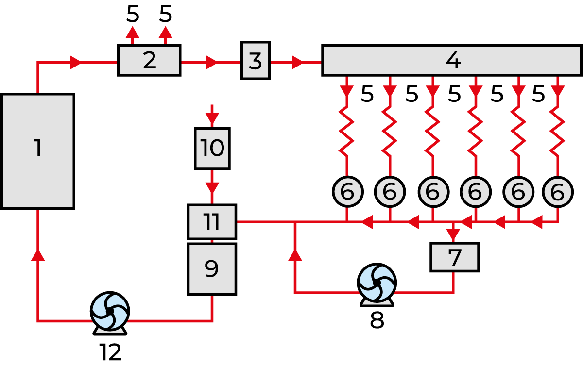
Fig. 8.3.4 Steam production and distribution system
1 Boiler 7 Condensate tank
2 Steam distribution vessel for high-pressure steam 8 Condensate pump
3 Pressure-reducing valve 9 Feed-water tank
4 Distribution vessel for low-pressure steam 10 Water softening filters
5 Points of consumption 11 Feed water degassing unit
6 Steam traps 12 Feed water pump
The water used for the generation of steam is referred to as feed water. Makeup water often contains calcium salts, which make the water hard. Treatment of feed water is often necessary, as it contains oxygen and carbon dioxide.
If this is not done, the salts will be deposited in the system and form scale in the boiler, resulting in drastically reduced efficiency. Oxygen can cause severe corrosion in the water and steam parts. Water-softening filters (10) are therefore included in the system.They remove the calcium and magnesium salts, and a de-gassing apparatus (11) removes the gases in the feed water. Impurities in the form of sludge are removed by blowing down the boiler. Chemical conditioning of boiler water and treatment of boiler feed water is necessary to keep the steam system in good operating condition.
A feed water pump keeps the water in the boiler at a constant level. The water in the boiler is heated by the burning fuel and converted to steam. It takes a great deal of heat, about 2,260 kJ (540 kcal) at atmospheric pressure, to convert one kilogram of water to steam. This heat, which is referred to as vaporisation heat, will subsequently be released as the steam condenses on the heat transfer surfaces at the points of consumption (5).
The condensed steam, condensate, is collected in steam traps (6) and a condensate tank (7) and pumped back to the boiler by a condensate pump.
Steam boilers
Two main types of boilers are used for the generation of steam: the fire tube boiler (which is the most common type in dairies) and the water tube boiler. The choice is influenced by the required steam pressure and steam power, i.e. the quantity of steam utilised at a given time. Boilers for low pressures and small power outputs are often fire tube boilers in which the flue gases pass inside the tubes. Boilers for high pressures and large steam power outputs are mostly water-tube boilers, in which the water is circulated inside the tubes.
Figure 8.3.5 shows the principle of the fire tube boiler. The hot flue gases are blown by a fan through the tubes. The heat from the flue gases is conducted through the walls of the tubes to the water surrounding the outside of the tubes. The water is heated to boiling point and the steam is collected in the steam dome for distribution to the system.
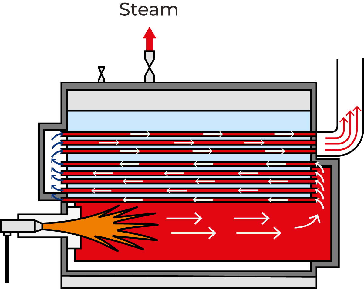
Fig. 8.3.5 Principle of the fire tube boiler.
When the pressure inside the steam dome reaches the required (preset) level, the steam valve can be opened and the steam flows to the points of consumption. The burner is started and stopped automatically, keeping the steam pressure at the required level. Feed water is added so that the correct water level is maintained in the boiler. The safety valve opens if the highest permitted pressure in the steam dome is exceeded. Water-tube boilers (Figure 8.3.6) are available in a wide range of models. The principle is that the feed water passes through tubes which are externally heated by the flue gases.
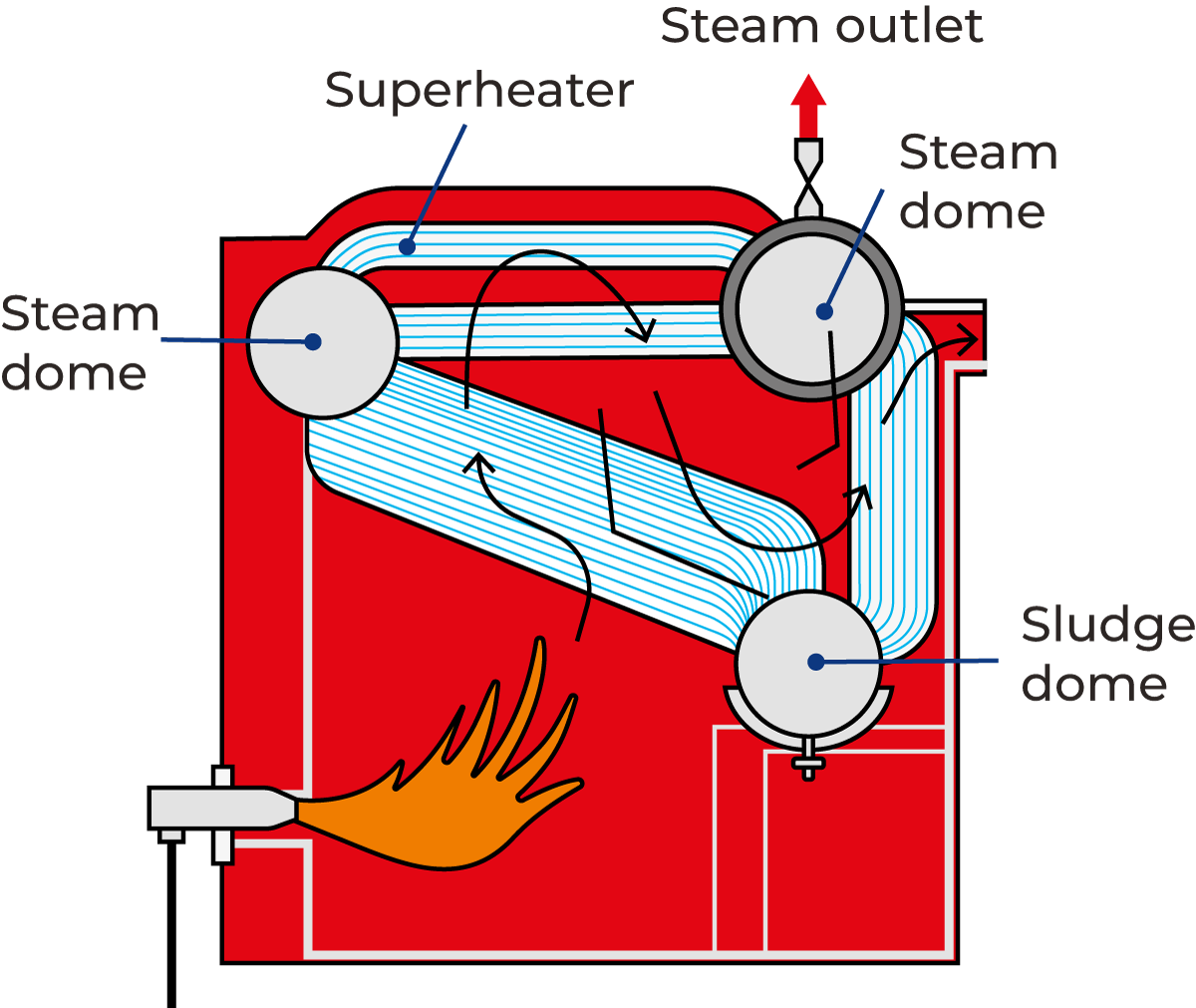
Fig. 8.3.6 Principle of the water-tube boiler including three steam domes.
Steam generation takes place in the tubes, which are inclined so that the steam can rise to the steam dome. The steam passes into the two upper domes via the superheater before being fed into the distribution system. The steam is heated by the flue gases for a second time in the superheater, i.e. the steam is superheated and becomes drier as a result. The lower dome also collects sediment sludge, the impurities which were present in the feed water. The sludge is removed from this dome by bottom-blowing the boiler. In other types of boilers, the sludge collects in the bottom of the boiler.
Collecting the condensate
The steam which passes through the piping system is cooled by the surrounding air and consequently starts to condense. It is possible to reduce this condensation by insulating the pipes, but condensation can never be completely avoided. The pipes must therefore be installed with a slight slope towards the condensate collection points, which are located in various parts of the piping system.
Steam traps are installed at these points. They permit the condensate to pass (and preferably also air), but not steam. The condensate is collected in the same way at the various steam consumption points and is returned to a collecting tank in the heating plant by condensate pumps and a piping system. Condensate can be returned to the feed water tank by steam pressure without using a condensate tank or condensate pump. This system is very often used.
Other equipment
The firing equipment of industrial steam boilers consists of a burner, (often an oil-fired burner of the atomiser type), in which the oil is dispersed as a fine mist. This mist is ignited by high-voltage electrodes and the resulting flue gases are blown through the boiler by a fan. Safety equipment is also included to eliminate the risk of accidents and damage. Modern steam-generating boilers are fitted with automatic control devices which permit operation without the need for constant supervision.
The steam piping system
A system for steam distribution and condensate collection is schematically shown in Figure 8.3.7. The steam passes through the main valve on the steam dome of the boiler to the distribution vessel via a pressure reduction valve. From here, the steam continues to the various points of consumption. A pressure-reducing valve is often fitted before the consumption point, for fine adjustment of the steam pressure. The steam piping system is exposed to extensive variations in temperature. This results in considerable thermal expansion of the pipes. The pipes must therefore be installed to permit axial movement.
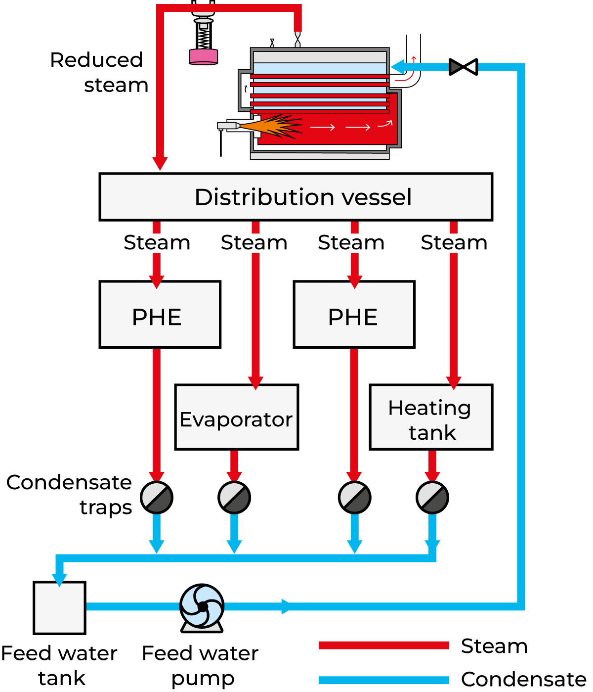
Fig. 8.3.7 System for steam distribution and condensate collection.
The location of the condensate trap and the design of the pipe system must be done with care to avoid the collection of water in the pipes. If a plug of water is formed, it will move through the pipe at high velocity, at least as fast as the steam, which is approximately 25 – 30 m/s. This is called a water hammer, and it can cause great damage to both pipes and valves.
Heat pump
A heat pump is a device that extracts heat from a heat source and delivers that heat (amplified) to a heat sink by utilising electrical energy. Heat is removed from the heat source (cooling side of the heat pump) and added to the heat sink (heating side of the heat pump) allowing for cooling and heating to be achieved.
A heat pump uses technology similar to that found in a refrigerator (described later) but in reverse, extracting heat from a source, then amplifying and transferring the heat to where it is needed.
Heat pumps are increasingly recognised as a critical technology for the decarbonisation of heat generation systems.
The efficiency of the heat pump is denoted by its COP (coefficient of performance), defined as the ratio of total useful energy delivered by the heat pump to the amount of electricity needed to drive the heat pump. A high COP value represents a high efficiency.
More information on heat pumps can be found in Chapter 4, Sustainability in dairy processing.
Refrigeration
Many stages in the process require that the product is heated to a certain temperature. Any increase in temperature will naturally result in increased activity by any microorganisms which may be present in the product, as well as speeding up the chemical reactions which are controlled by enzymes. Activity of this kind must be avoided as much as possible, so it is important to reduce the product temperature as soon as a particular stage of production has been completed. The need for refrigeration in dairies is consequently very great, and the operating costs of the refrigeration plant represent a significant item in the budget of any dairy.
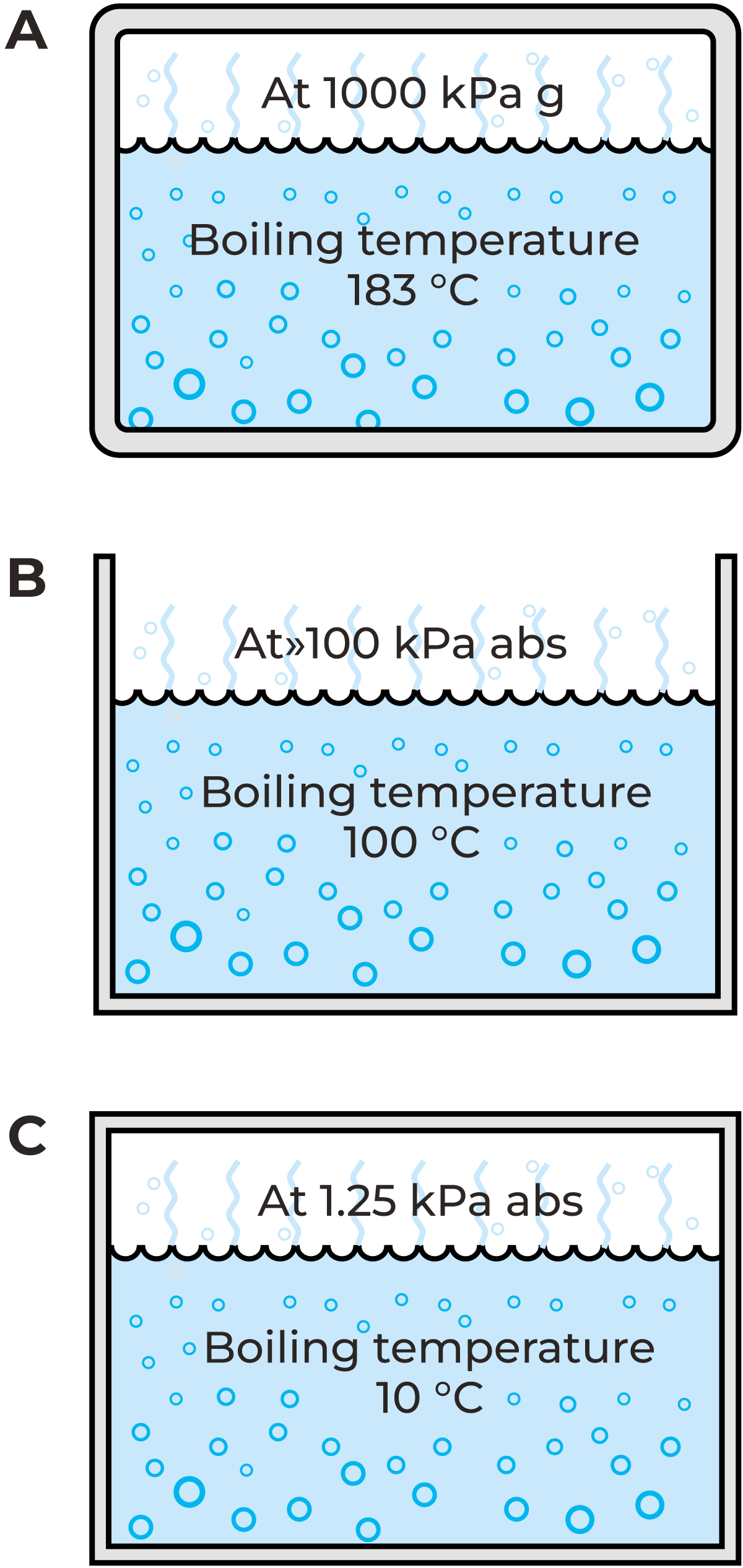
Fig. 8.3.8 Reduction of pressure causes water to boil at lower temperatures. (g = gauge).bution and condensate collection.
The principle of refrigeration
The refrigeration effect is based on the fact that heat is absorbed when a liquid is converted into vapour. This phenomenon, vaporisation heat, has already been mentioned in the description of the steam boiler. The internal pressure of the steam boiler is higher than atmospheric pressure and the water therefore boils at a higher temperature; water at a gauge pressure of 1,000 kPa (10 bar) boils at 183 °C. See Figure 8.3.8 (A).
Conversely, water boils at a lower temperature if the pressure is reduced. Water at atmospheric pressure boils at 100 °C. See Figure 8.3.8 (B). If the pressure is reduced to below atmospheric pressure, a vacuum is created and the water boils at a temperature below 100 °C. Water can be made to boil at about 80 °C by connecting a vacuum pump to a vessel containing water and reducing the absolute pressure to 50 kPa (0.5 bar). Water will boil at 10 °C if the pressure is reduced to 1.25 kPa (0.0125 bar), as shown in Figure 8.3.8 (C). If this vessel is placed in an insulated room in which the air temperature is 20 °C, heat from the air will be transferred to the water in the vessel. The water will then be converted to steam. If the steam formed in this way is continuously extracted so that the pressure inside the container does not exceed 1.25 kPa, the air in the room will be cooled by the transfer of heat to the water in the vessel, the water acts as a refrigerant.
1.25 kPa is very low, and it would therefore be extremely expensive to use water as a refrigerant. There are other liquids which boil at the same temperature under considerably higher pressures. Such a liquid has a higher vapour pressure than water. One example is ether; if a drop of ether falls on the skin, it feels cold. This is because heat from the skin is transferred to the liquid ether as it boils and is converted to vapour. Ether boils at a temperature below 37 °C at atmospheric pressure. If the pressure at the surface of the liquid is reduced by a vacuum pump, such liquids can be made to boil at temperatures well below 0 °C.
Ammonia is a common refrigerant. It boils at atmospheric pressure at a temperature of about –33 °C. If the pressure is reduced to 50 kPa (0.5 bar), ammonia boils at –45 °C.
How refrigeration works
A refrigeration system is a closed circuit in which the refrigerant cycles between gaseous and liquid form by undergoing alternate pressure reduction (expansion) and pressure increase (compression).
The principal components of the system are:
- Evaporator
- Compressor
- Condenser
- Expansion valve
Figure 8.3.9 shows how the system operates. The refrigerant is under low pressure in the evaporator, where it absorbs heat from the surrounding space. This causes part of the refrigerant to vaporise continuously. The vapour is continuously extracted from the evaporator by the compressor, which thus keeps the pressure of the refrigerant and its vaporisation temperature at a constant level.
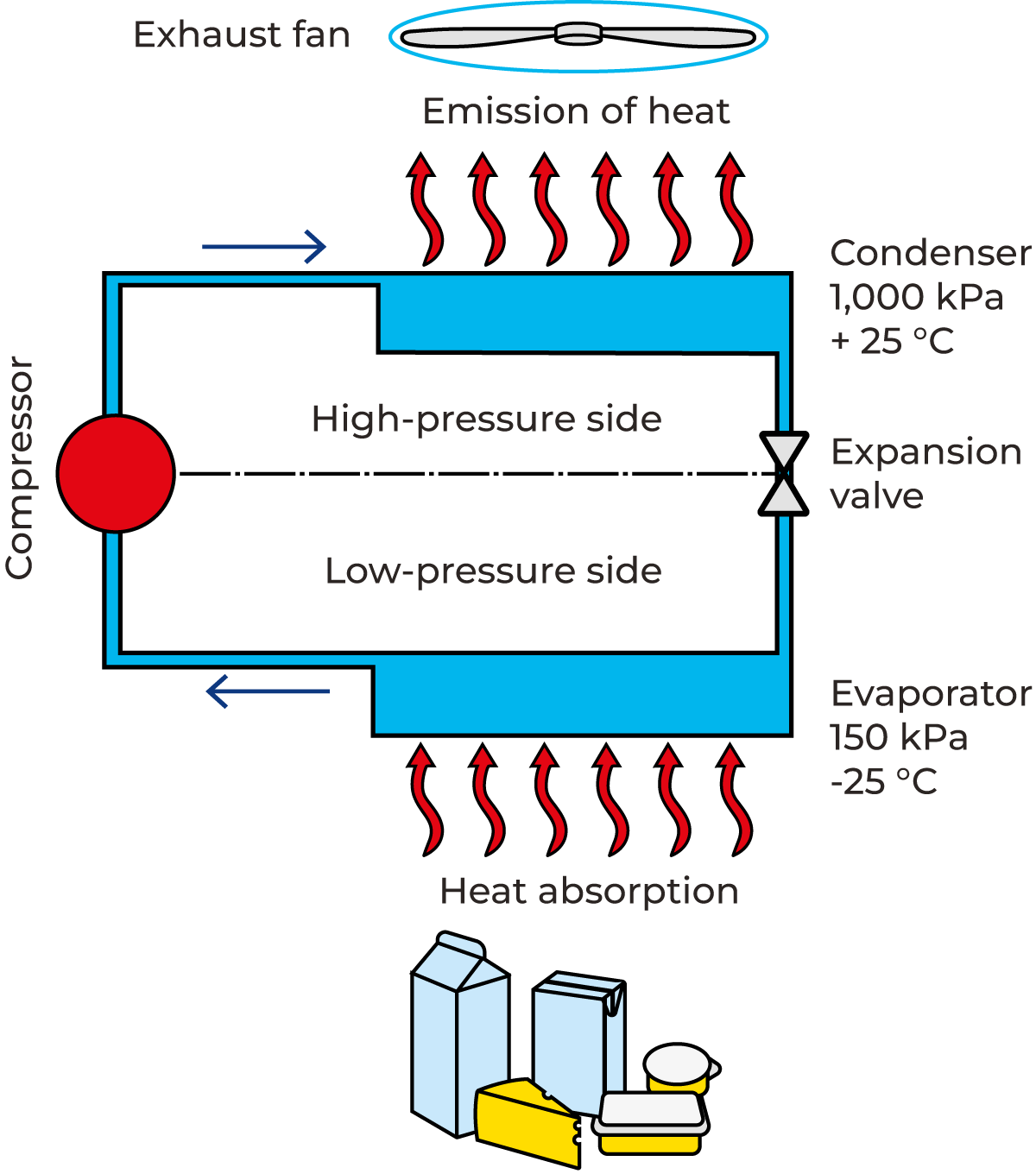
Fig. 8.3.9 Representation of a refrigeration system with ammonia refrigerant.
The vaporised refrigerant is compressed to a higher pressure in the compressor. The hot refrigerant gas is then forced from the compressor to the condenser for cooling, where the heat is transferred to the ambient air or water sink. Compression causes both the vaporisation temperature and the condensation temperature of the refrigerant vapour to rise.
Where ammonia is used, the operating vaporisation temperature is often about –20 °C, which corresponds to a vaporisation pressure of 200 kPa (2 bar) absolute.
The pressure of the boiled-off gas is boosted to about 1,000 kPa (10 bar) in the compressor. This corresponds to a vaporisation temperature of +25 °C. The ammonia gas then condenses, i.e. it changes from a vapour to a liquid. This is done in the condenser by cooling the gas with water or air. The heat absorbed by the ammonia in the evaporator is released in the condenser.
The condensed liquid ammonia must then be returned from the condenser to the evaporator. The liquid passes through the expansion valve in order for the pressure to be reduced. This also reduces the temperature of the liquid. The expansion valve is set to give an exact reduction in pressure (so that the liquid assumes the same pressure as in the evaporator). A small proportion of the liquid vaporises in the expansion valve when the pressure is reduced. The vaporisation heat which this requires is obtained from the liquid, which is consequently cooled.
The evaporator
The evaporator is the part of the refrigeration plant in which the evaporation of the refrigerant takes place. The design of the evaporator is determined by the selection of refrigerant.
There are three main types of evaporators used in dairies:
- Air-circulation evaporators
- Shell-and-tube and plate-type evaporators
- Coil evaporators for ice accumulation
In air-circulation evaporators (Figure 8.3.10), air is chilled by being passed through a fin-and-tube coil to maximise their heat-transfer area. The refrigerant circulating in the tubes absorbs heat from the air and is vaporised. Air-circulation evaporators are used for refrigeration of storage areas and for cooling the air in air-conditioning plants.
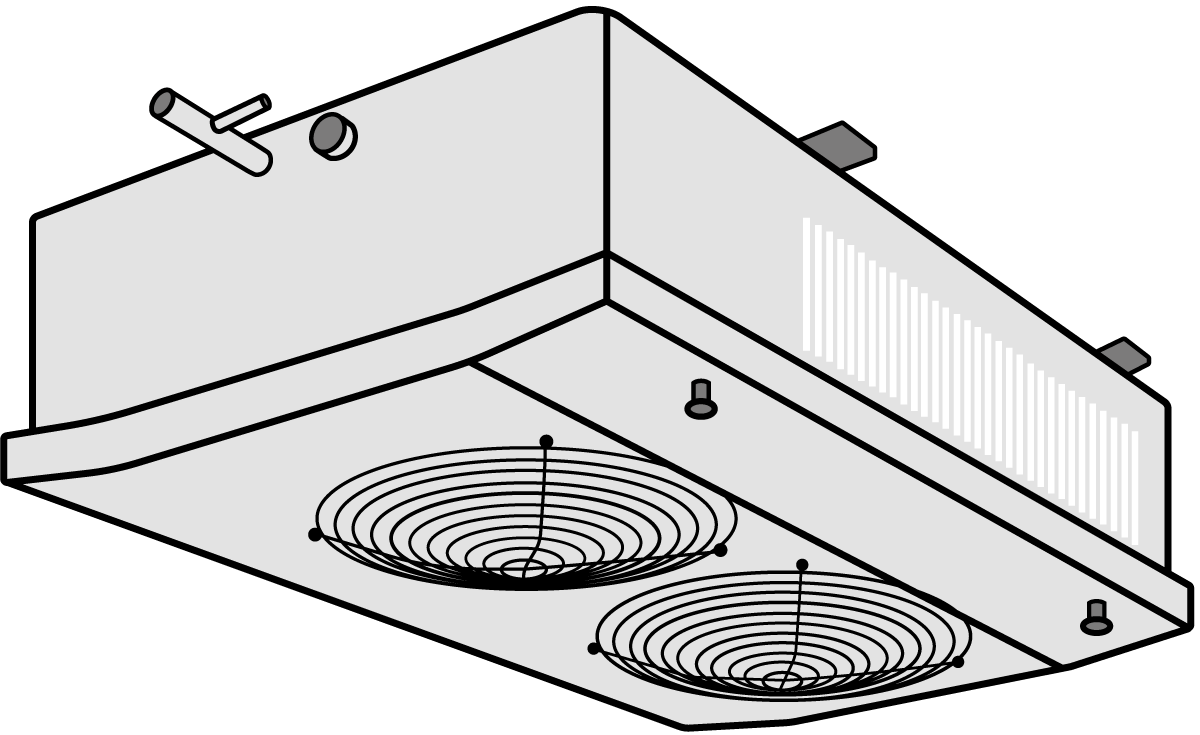
Fig. 8.3.10 A small air cooler.
Shell-and-tube and plate-type evaporators are widely used in dairies, where their function is to extract heat from the circulating coolants that cool products in process heat exchangers. Such coolants include ice water, brine (salt water) and alcohols such as ethanol and glycol, which have freezing points below 0 °C.
The coil evaporator (Figure 8.3.11), for ice accumulation, is designed to be placed in a water vessel to produce ice water. During the night, water freezes in a layer on the evaporator tubes, inside which the refrigerant is circulated. This makes it possible to use cheap electric energy for running the cooling plant. The ice melts during the day, permitting a great deal of refrigerating capacity to be removed from this “ice bank” in the form of ice water.
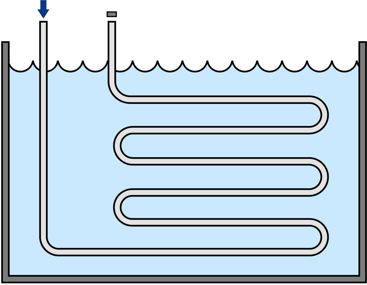
Fig. 8.3.11 Ice water tank with evaporator coils.
The compressor
The refrigerant vapour is compressed to a high pressure in the compressor. This increases the temperature of the vapour. The work carried out by the compressor is transferred to the gas in the form of heat. This means that the gas leaving the compressor contains a greater quantity of heat than was absorbed in the evaporator. All this heat must therefore be removed by cooling in the condenser. The most commonly used refrigerating compressor is the piston compressor. The gas is drawn into cylinders and compressed by pistons in the cylinders. The machines can be equipped with a varying number of cylinders. They are available for refrigerating capacities between 0.1 and 400 kW.
The screw compressor (Figure 8.3.12), is also very common nowadays, especially for higher capacities. The principal components are two helical rotors installed in a common housing. As the rotors turn, gas is drawn into the gaps between the teeth (see the text on positive displacement pumps in the Pumping demands section of Chapter 7.8) and is trapped in the clearances. The volume between the teeth is progressively reduced as the captive gas is conveyed along the length of the rotors, so the gas is gradually compressed and the pressure increases. The compressed vapour continues to the condenser. Oil is sprayed on the meshing faces in most screw compressors in order to reduce leakage between the gaps in the rotors. In this way, it is possible to obtain high efficiency even at low speeds. The oil is removed from the vapour in an oil filter before the condenser.
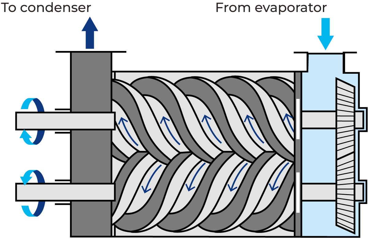
Fig. 8.3.12 Design principle of the screw compressor.
Screw compressors are used in large installations. One of the greatest advantages of the screw compressor is that the capacity can be varied down to 10% of full power without excessive electric power losses.
The condenser
The heat absorbed in the evaporator and the heat transmitted to the vapour in the compressor are removed by cooling in the condenser.
Condensers are divided into three types:
- Air-cooled condensers
- Liquid-cooled condensers
- Evaporation condensers
The selection of the condenser is determined by external factors such as water supply, the price of water, the operating time of the plant, and ambient conditions (the climate).
Air-cooled condensers have, until now, mostly been used in small refrigeration plants, but are becoming more common in large plants. The reason for this is the rapidly increasing cost of water and, occasionally, the uncertainty of the water supply. In the air-cooled condenser, the refrigerant passes through a fin-andtube heat exchanger, around which the cooling air circulates. As it is cooled, the refrigerant condenses in the coil and then flows to the throttling valve.
The water-cooled condenser is the most economical type where a cheap supply of water is available. The most common type is the tube condenser (Figure 8.3.13). It operates by circulating cooling water inside the tubes. This condenses the refrigerant on the external tube surfaces.
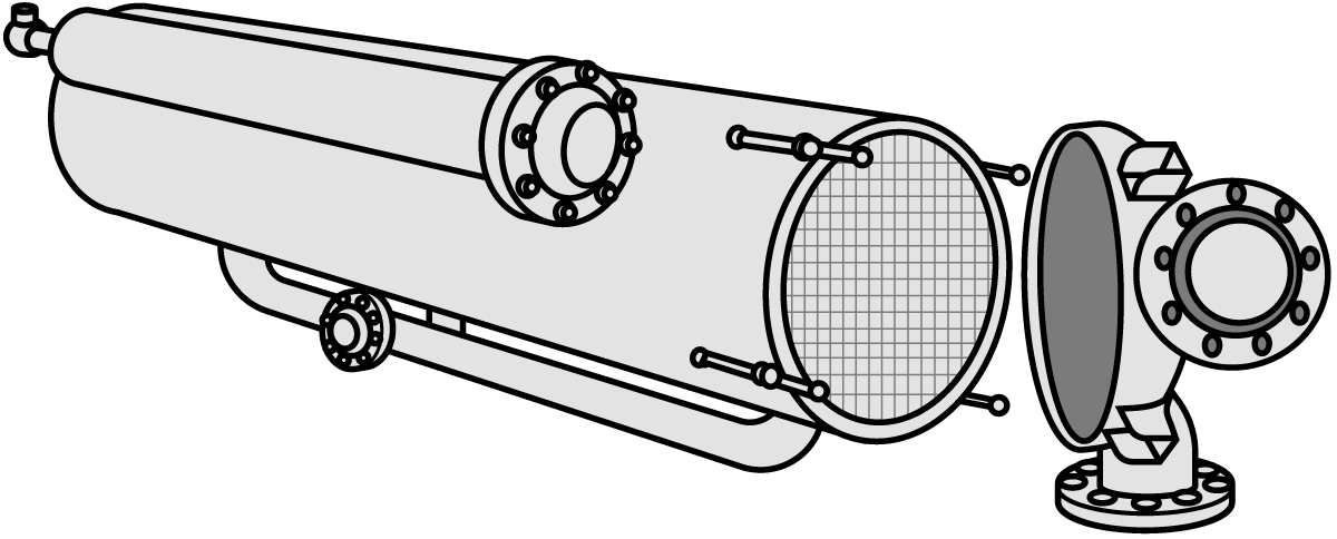
Fig. 8.3.13 Tube condenser.
The water-cooled condenser (Figure 8.3.14) is often combined with a cooling tower. The cooling water is cooled by air in the cooling tower and is then pumped to the condenser, where it absorbs the condensation heat from the refrigerant. From there, it is pumped back to the cooling tower for the air-cooling to be repeated.
The evaporation condenser is a combination of an air-cooled condenser and a cooling tower. This type is used when there is a shortage of cooling water or where the cost of cooling water is too high.
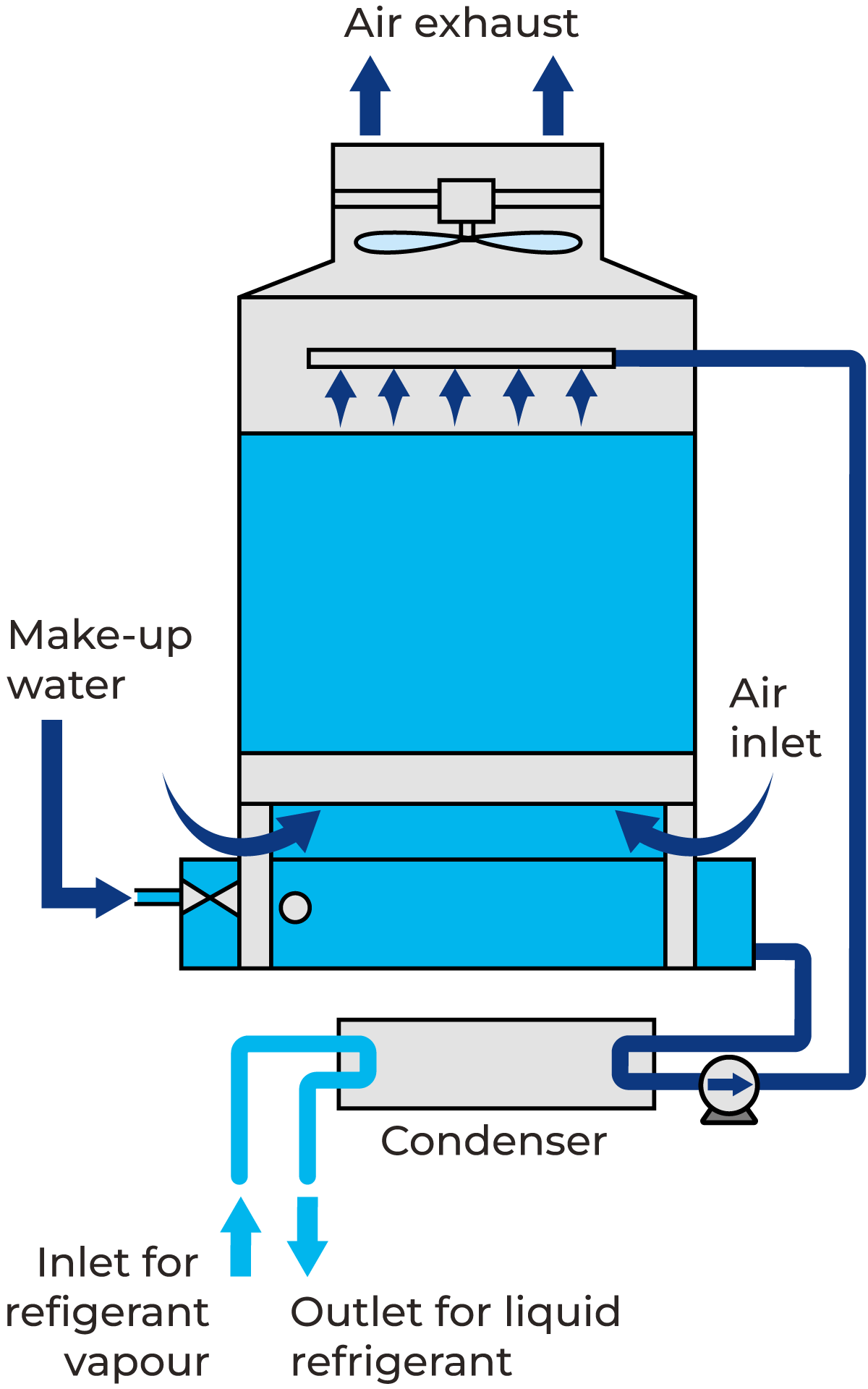
Fig. 8.3.14 Combined tube condenser and cooling tower circuit.
Other equipment
The installation described has been greatly simplified to illustrate how the refrigeration plant works. Many other components are required in order for the plant to function, e.g. refrigerant tanks, filters, oil traps, safety valves, shut-off valves, level, pressure and temperature gauges and other forms of safety equipment in order to permit safe operation of the plant. The plant can also be equipped with automatic control devices to eliminate the need for constant supervision and to provide more economical operation.
Cooling systems in dairies
Ice water is the most common form of cooling water used in dairies. Water is cooled in an ice water tank where ice is formed on evaporator coils. A glycol system is used when low temperatures are required that cannot be achieved with water as cooling media. A typical solution contains 30% of glycol and 70% of water. This solution has a freezing point of about –13 °C. Glycol used in the food industry shall be propylene glycol and if there is any possibility that it can come in contact with product all additives shall be non-toxic. These additives are added as corrosion protection and to stabilise the glycol. Cooling towers are used to get cooling water that is close to the wet bulb temperature of ambient air. In a cooling tower, water is sprayed inside the tower. Air is drawn through the falling water, causing a portion of it to evaporate, which cools the remaining water. The cooled water is collected in a basin at the bottom of the tower. The process has a low energy demand and can be a cheap way to get low-grade cooling water.
Pipe systems for cooling water
If pipes that are not rustproof are used, they must be protected against rust by painting. Insulation shall stand moisture and shall include a vapour barrier to avoid condensation inside the insulation.
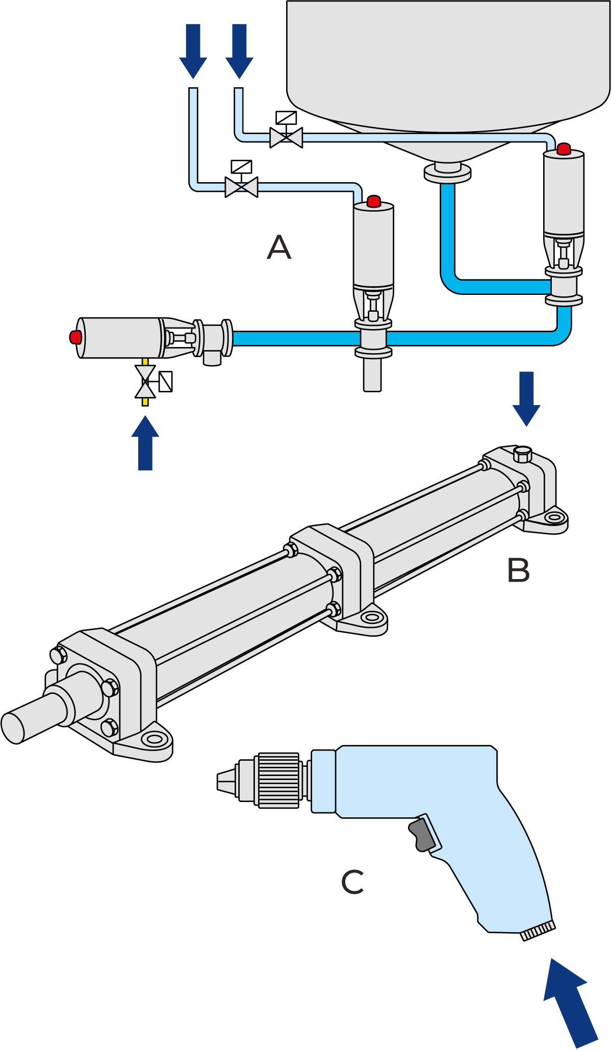
Fig. 8.3.15 Compressed air has many applications in the dairy.
A Air for actuating valves
B Air for powering cylinders
C Air for pneumatic tools
Production of compressed air
The dairy industry has an extensive requirement for advanced instruments and equipment for automatic control, monitoring and regulation of the various production processes. Pneumatically controlled automatic systems have proved reliable in the damp atmosphere of the dairy and are frequently used. Reliability requires compressed air free from impurities, which makes demands on the design of the compressed-air system.
Compressed air also has other applications:
- Powering the actuators in some machines, such as filling machines
- Emptying product from pipes
- Agitation in storage tanks
- Pneumatic tools in the workshop
Demands on compressed air
The various applications for compressed air in the dairy make different demands concerning air pressure, dryness, purity and quantity. Based on the requirements for purity, compressed air is divided into three quality classes:
- Compressed air which comes into direct contact with the product. This class should be clean, oil-free, dry, odourless and practically sterile. Relatively small quantities of this A-quality air are used. The supply pressure is often between 200 and 300 kPa (2 – 3 bar).
- Compressed air which does not come into contact with the product, but still must be clean, dry and preferably oil-free, as it will be used for the control of instruments and as the source of power to actuate pneumatic components and valves, etc. This compressed air is supplied at a pressure of between 500 and 600 kPa (5 – 6 bar).
- Compressed air which should be free from solid particles and as dry as possible, as it will be used for pneumatic tools, etc. The supply pressure is approximately 600 kPa (6 bar).
Untreated air from the atmosphere always contains impurities. These are found in untreated compressed air, together with impurities from the compressor. There may be particles produced from wear and from oil particles. Atmospheric air also contains water vapour, which must be removed if the compressed air is to meet the necessary standard of quality.
The largest quantities of compressed air are used for pneumatic machines in the dairy and in the workshop. This air must be supplied at a pressure of approx. 600 kPa (6 bar), for which a compressor plant producing an operating pressure of 700 kPa (7 bar) is required to compensate for the pressure drop in the distribution system. Only a small quantity of compressed air is needed at pressures lower than those required for the control of instruments and as a source of power. It would therefore be uneconomical to use separate compressors for this air, as it would also require a separate system of air conduits. Consequently, compressed air for all applications is taken from the central compressor plant and then receives individual treatment to meet the several requirements of its applications.
The compressed-air installation
Compressed air is produced in an air compressor. When air must be oil-free, it is not possible to use compressors in which the compression chamber is lubricated with oil to increase compression efficiency. Oil-free compressors must be used. It is practically impossible to remove all the oil from compressed air, but it is nevertheless possible to obtain a remaining oil content of only 0.01 ppm. It is normal to use two identical compressors to meet the overall compressed-air requirement of the dairy.
The types of compressors used include oil-lubricated compressors, screw compressors with oil-free compression chambers, special piston compressors with non-lubricated cylinders and a means of preventing oil from the crankcase from entering the compression chamber, and finally turbo compressors.
Figure 8.3.16 shows an example of an installation. Air is supplied from the compressor to a dehumidifier, where the water vapour in the air is removed by cooling and precipitation. The dried air then continues to an air receiver. The compressed air is taken from this tank and used to control instruments, operate valves and power actuating cylinders, etc.
Compressed air of the highest quality, which comes into direct contact with the product when used for pneumatic agitation of tanks and for emptying product from pipes, undergoes further drying in adsorption filters and is then sterilised in special filters before being used.
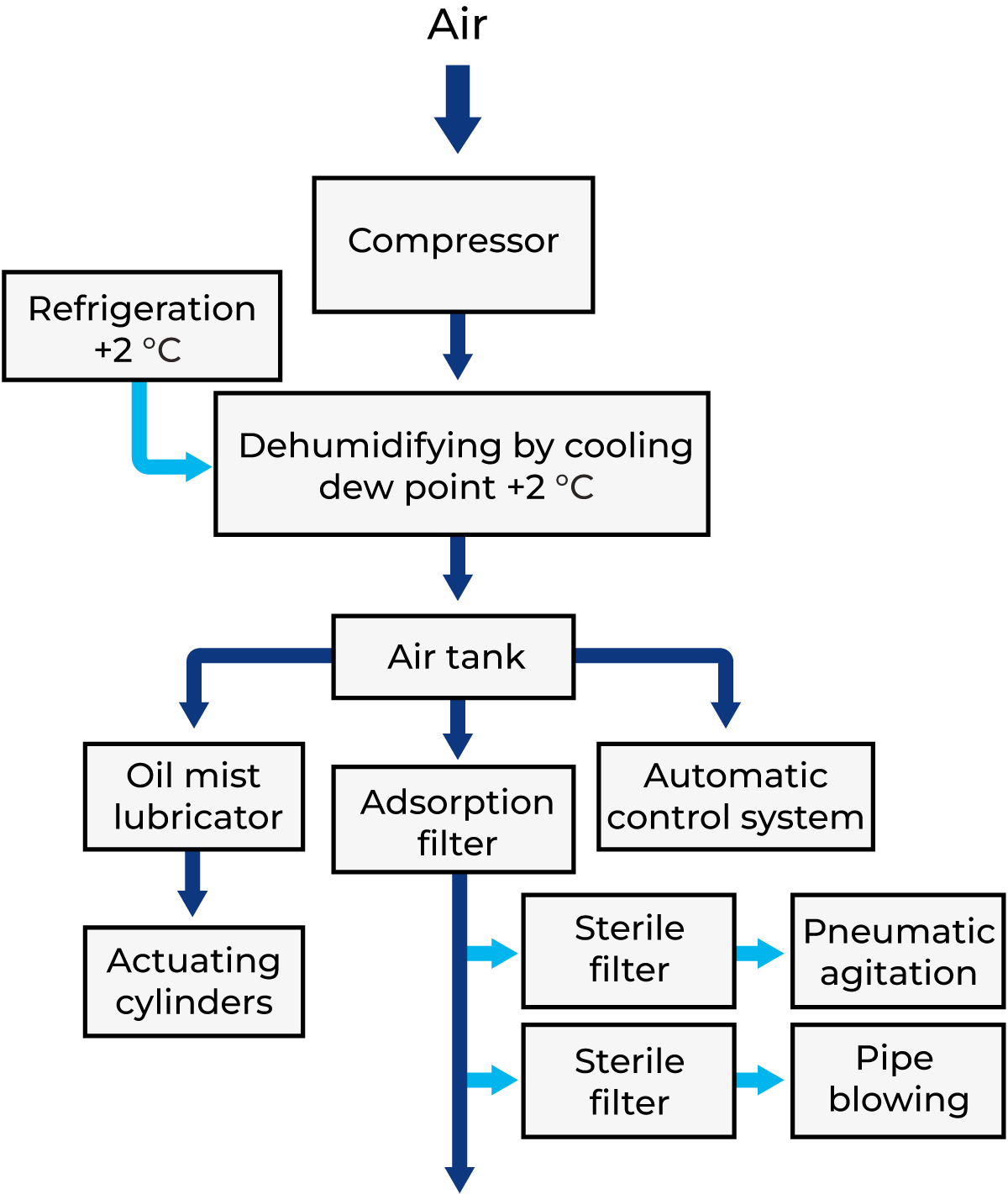
Fig. 8.3.16 Compressed-air block diagram.
Pipe system
The most rational solution is to have a single compressor plant and a single distribution network for the compressed air. It is of the greatest importance in a modern, highly automated dairy that instruments and control systems can always be supplied with compressed air at the correct pressure and in the correct quantity. In some cases, the design may involve the installation of regulators which supply compressed air to the control system, so that the air supply to less sensitive points can be shut off if there is a tendency for the pressure in the supply line to drop.
Electric power
Dairies normally purchase their electric power from local distributors. In most cases, it is supplied at high voltage, between 3,000 and 30,000 V, but dairies with a power demand of up to approximately 300 kW may also take low-voltage supplies of 240/440 V.
The principal components of the electrical system are:
- High-voltage switchgear
- Power transformers
- Low-voltage switchgear
- Generating set
- Motor control centres (MCC)
High-voltage switchgear
The high-voltage switchgear is the main panel for high-voltage distribution.
The switchgear consists of a number of cubicles with a central busbar system to which various types of switches are connected. One or more cubicles are used for the incoming supply from the distributor. Each supply/cubicle has a switch for isolation. After the incoming cubicles, there is a cubicle with equipment for metering the electric energy used. After the metering cubicle, come cubicles for outgoing supply, one per transformer/supply. A normal dairy has between one and four transformers. Each transformer is protected by a switch (circuit breaker or load disconnector and fuse) that cuts off the power in case of fault or overload.
If the dairy has very large motors, for instance, 300 kW and above, it may be worthwhile to supply them with high voltage from separate cubicles in the switchgear.
Power transformer
The power transformer receives power from cables connecting it to the high-voltage switchgear. The power transformer converts high-voltage to lowvoltage, normally between 230 and 440 V. The size of the transformer depends on the power demand. The normal capacity range is 400 – 2,000 kVA.
There are two main types of transformers:
- Oil-insulated for indoor and outdoor installation
- Dry-insulated for indoor installation
Oil-insulated transformers are less expensive but require a separate, fireproof room because of the inflammable oil. The room should have a sump under the transformer, where leaking oil can be collected.
Dry-insulated transformers do not contain inflammable oil and can therefore be installed in connection with the load. Transformers are subject to losses of approximately 1 kW per 100 kVA. This lost energy is given off as heat, which must be removed by ventilation.
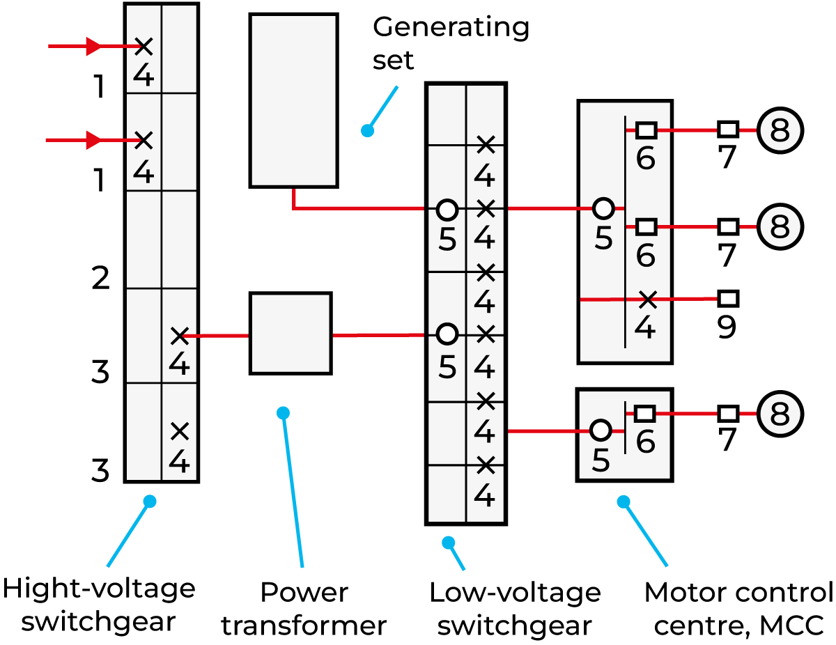
Fig. 8.3.17 Example of a power distribution system for a dairy plant.
1 Cubicle for incoming supply
2 Cubicle for metering equipment
3 Cubicle for transformer supply
4 Circuit breaker
5 Main switch
6 Motor starter
7 Isolating switch
8 Consumption point (motor)
9 Remote control panel
Low-voltage switchgear
The low-voltage switchgear receives power from cables or bars connecting it to the power transformer. The low-voltage switchgear is the main panel for low-voltage distribution; it contains equipment for switching, controlling and protecting outgoing supplies.
The size of the power transformer determines how big the main switch and busbar system of the switchgear must be.
The switchgear contains:
- One incoming unit with a main switch for isolation of the switchgear plus instruments for control of voltage, current, etc.
- Several outgoing units to large power consumers such as motor control centres (MCC), homogenisers, etc. Each supply has a circuit breaker or load breaker and a fuse for the protection of cables and apparatus.
- One unit with power factor correction equipment (not always).
Generating set
A generating set can be used for local production of electric power. The generating set may run continuously or be used as a standby if the local distribution system is out. The generator is usually diesel-powered, has its own integrated control panels, and delivers a low-voltage supply. Several generating sets can run in parallel if needed.
Motor control centre (MCC)
The MCCs receive power from cables connecting them to the low-voltage switchgear. The MCCs control, protect and distribute power to the final consumption points in the plant. An MCC contains one incoming unit with a main switch for isolation and outgoing units for supply to machines and motors.
The most common types of supplies are:
- One or three-phase circuit breakers (or fuses)
- Motor starters for direct online start
- Variable speed drives (via frequency converters)
Normally, a number of connection points are supplied from an MCC. Some machines have an enclosed MCC/ control panel with all the necessary equipment.
An MCC can be controlled:
- Manually by pushbuttons on the front
- Manually by pushbutton panels located in process areas
- By electronic control systems inside the MCC or in a central control room
Individual machines and motors receive power from cables connecting them to the MCCs. The cables are normally installed on cable trays or in pipes. An isolating switch (safety switch) is installed close to each motor for use during servicing.
All material used must have a suitable protection (IP = ingress protection classification) against contact with solid objects and ingress of water, depending on the room (surroundings) in which it is installed. International standards are available as a help for this classification. Normally, IP 54 is required within process and packaging areas.
Design of electrical installations
When designing the above electrical installations, one has to follow domestic laws, regulations and standards. Today most national standards, etc. comply with international standards. Some of these standards are mandatory, which means that one must follow them. Some standards are only recommendations.
The organisation handling international electrical standards is the IEC, International Electrotechnical Commission. IEC was founded in 1906 and has taught electricians to speak one common language and to design similarly to each other. In Europe, there is also the European organisation, CENELEC, the European Committee for Electrotechnical Standardisation.
Within the EU countries, there are also some EU directives one has to follow, such as the Machinery Directive, Low Voltage Directive and the Electromagnetic Compatibility Directive. Manufacturers following these directives can put the CE mark on their equipment.
Electrical plants are also designed with respect to different earthing/wiring systems.
TN power systems have one point directly earthed at the source; the exposed-conductive parts of the installation are connected to that point by protective conductors. Three types of TN systems are considered according to the arrangement of neutral and protective conductors, as follows:
- TN-S system in which, throughout the system, a separate protective conductor is used
- TN-C-S system in which neutral and protective conductor functions are combined in a single conductor in a part of the system
- TN-C system in which neutral and protective conductor functions are combined in a single conductor throughout the system
The TT system has only one point directly earthed, and the exposed-conductive-parts of the installation are connected to earthed electrodes electrically independent of the earthed electrode of the supply system.
The IT power system has all live parts isolated from earth or one point connected to earth through an impedance. The exposed-conductive-parts of the electrical installation are earthed independently or collectively or to the earthing of the system accordingly.
The most common system is a combination of two of the above systems, the TN-C-S system, which is a combination of the TN-C and TN-S systems. In this case, it is normally a TN-C system up to the motor control centres and a TN-S system inside the MCC, as well as after them, out to the process, filling and packaging plant.
Today electrical systems have become more complex with high demands on safety and precision. The use of noise-generating devices, such as frequency converters, has increased the general noise level on the electrical supply. Modern control systems are also more complex and of course, one has to install both the electrical system and the control system in a correct and coordinated way. Here, correct earthing/grounding and cable installations are especially important.