Pipes, valves and fittings
The pipe system
The product flows between the components of the plant through the pipe system.
A dairy also has conduit systems for other media such as water, steam, cleaning solutions, coolant and compressed air. A waste-water system leading to the drain is also necessary. All these systems are basically built up in the same way. The difference is in the materials used, the design of the components and the sizes of the pipes.
All components in contact with the product are made of stainless steel. Various materials are used in the other systems, e.g. cast iron, steel, copper and aluminium. Plastic is used for water and air lines, and ceramic for drainage and sewage pipes.
The following section deals only with the product line and its components. The pipe systems for service media are described in the section dealing with utility installations.
The following types of fittings are included in the product pipe system:
- Straight pipes, bends, tees, reducers and unions
- Special fittings such as sight glasses, instrument bends, etc.
- Valves for stopping and directing the flow
- Valves for pressure and flow control
- Pipe supports
USA AISI 304 AISI 316 AISI 316L
Europe EN 1.4301 EN 1.4401 EN 1.4404
Connections
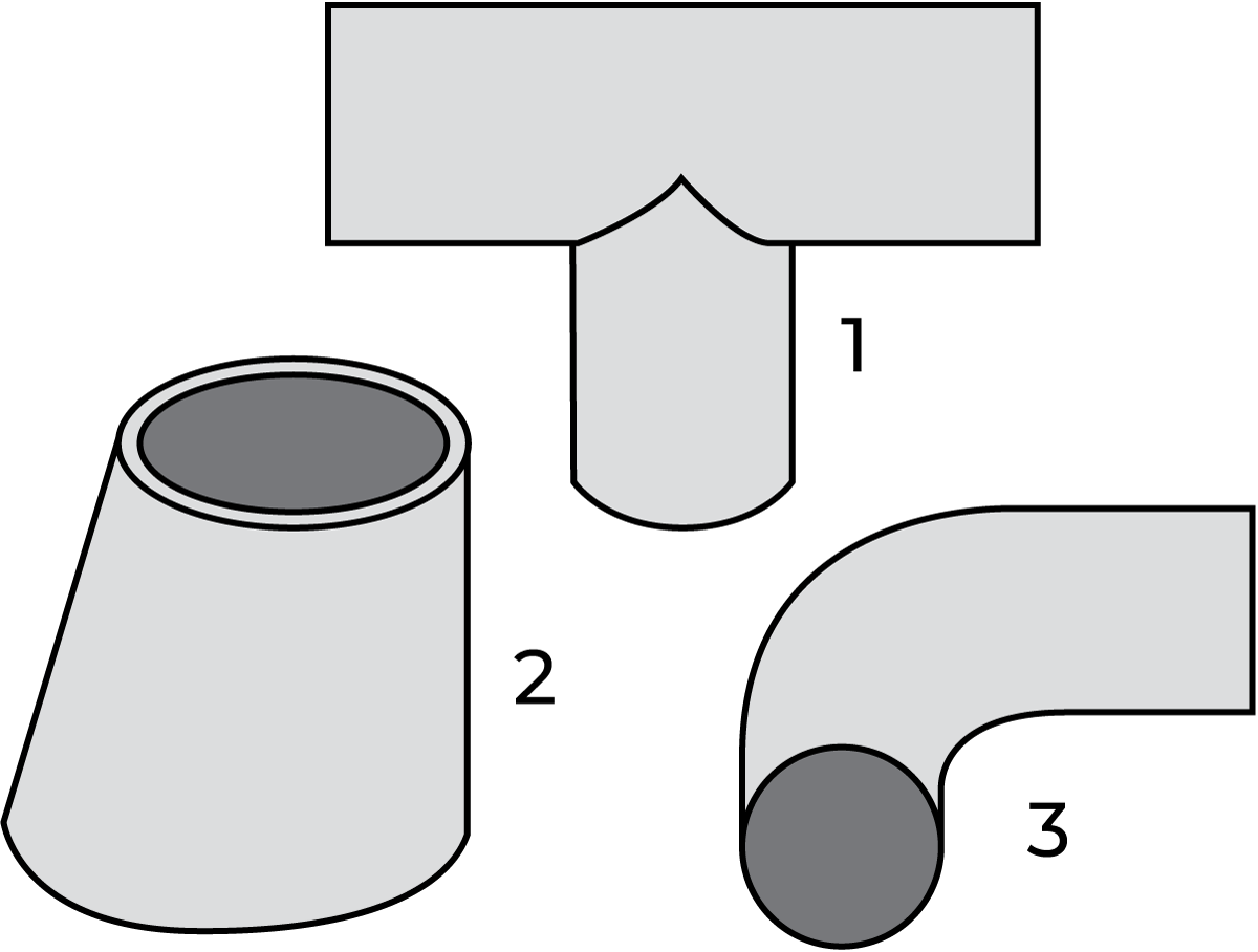
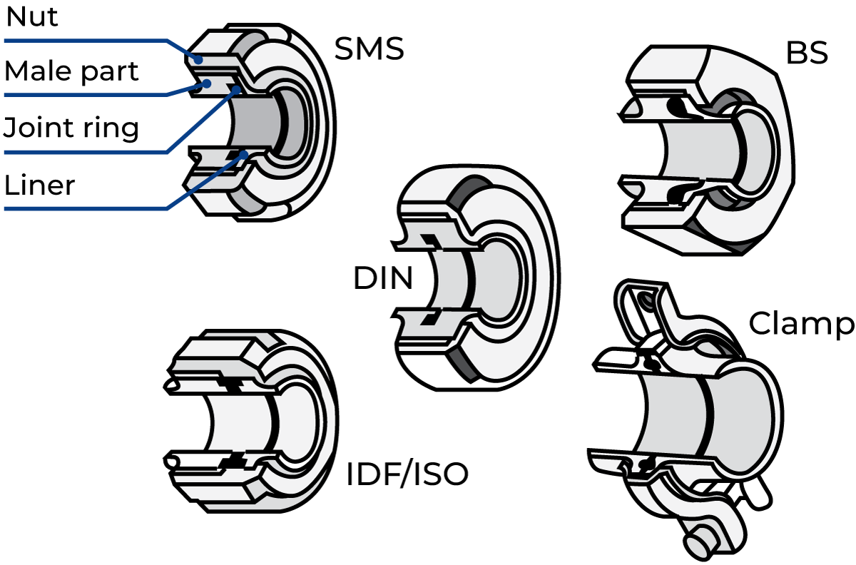
Permanent joints are welded (Figure 7.9.1). Where disconnection is required, the pipe connection is in the form of a threaded union with a male end and a retained nut with a joint ring in between, or a clamped union with a joint ring (Figure 7.9.2).
The union permits disconnection without disturbing other pipe-work. This type of joint is therefore used to connect process equipment, instruments, etc. that need to be removed for cleaning, repair or replacement.
Different countries have different union standards. These can be SMS (Swedish Dairy Standard) also used internationally, DIN (German), BS (British), IDF/ ISO* and ISO clamps (widely used in the USA).
ISO = International Organization for Standardization
Bends, tees and similar fittings are available for welding, and with welded unions. In the latter case, the fitting can be ordered with nut or male ends or with clamp fittings.
All unions must be tightened firmly to prevent liquid from leaking out or air from being sucked into the system and causing problems downstream.
Special pipe fittings
Sight glasses are fitted in the line where a visual check of the product is required.
Bends with instrument connections are used for fitting instruments like thermometers and gauges. The sensor should be directed against the flow to make readings as accurate as possible. The connection boss can also be used for a sampling cock. Instrument connections can also be provided with welding special bosses directly onto the pipe during installation.
Sampling devices
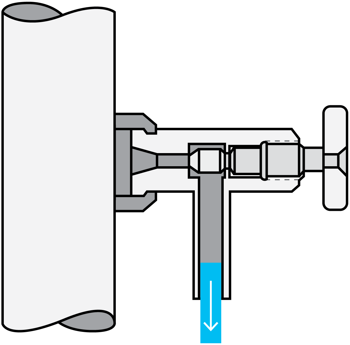
Sampling devices need to be installed at strategic points in the plant to collect product samples for analysis. For quality control, such as determining the fat content of milk and the pH value of cultured products, the samples can be collected from a sampling cock (Figure 7.9.3).
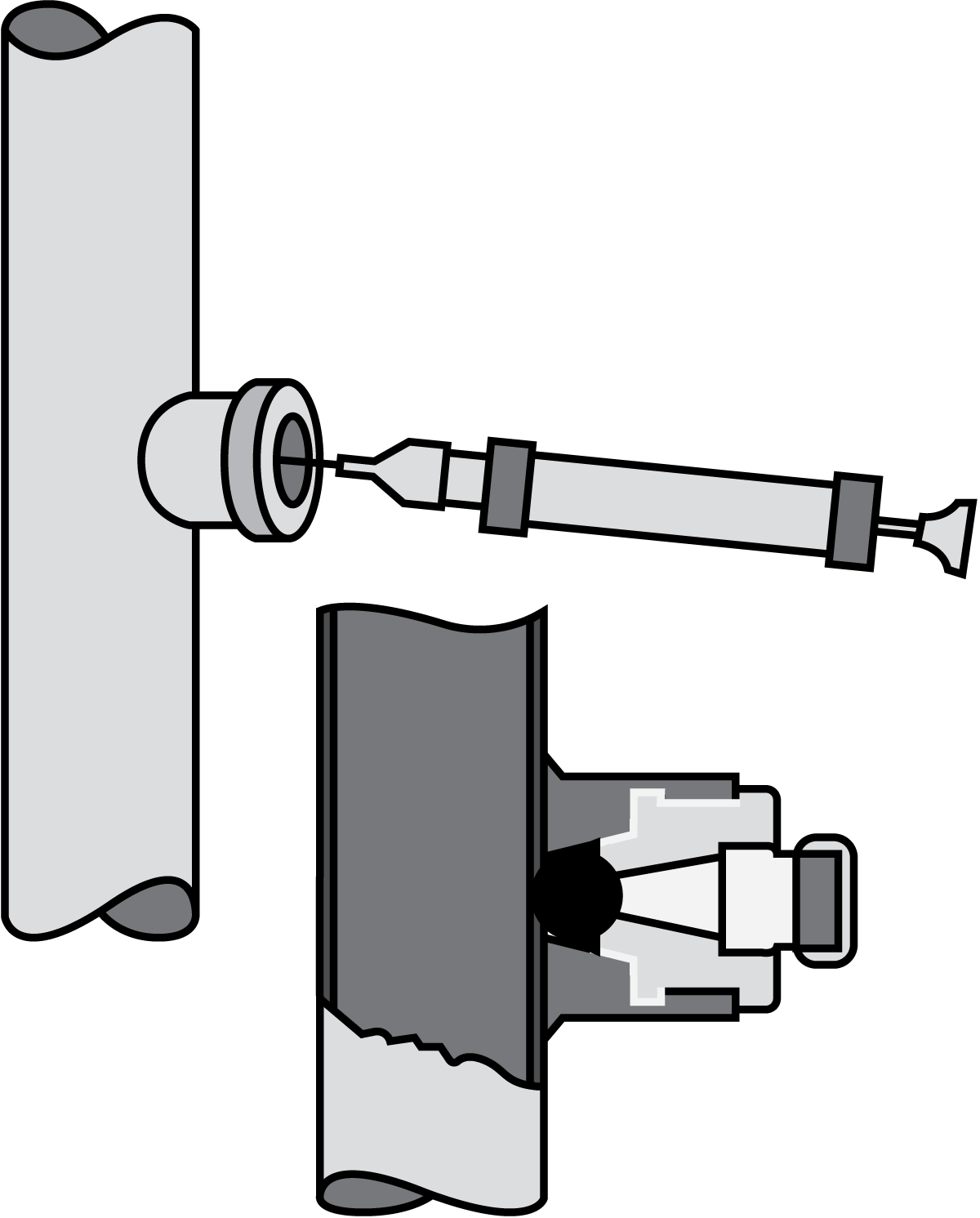
For hygienic quality tests, the sampling method must preclude any risk of contamination from outside the pipe. A sampling plug can therefore be used. This plug, shown in Figure 7.9.4, has a rubber bung at the bottom. The plug is first removed and all parts that could contaminate the sample are sterilised (typically with a wad moistened in a chlorine solution just before sampling), after which the needle of a hypodermic syringe is inserted through the bung into the product, and a sample is withdrawn.
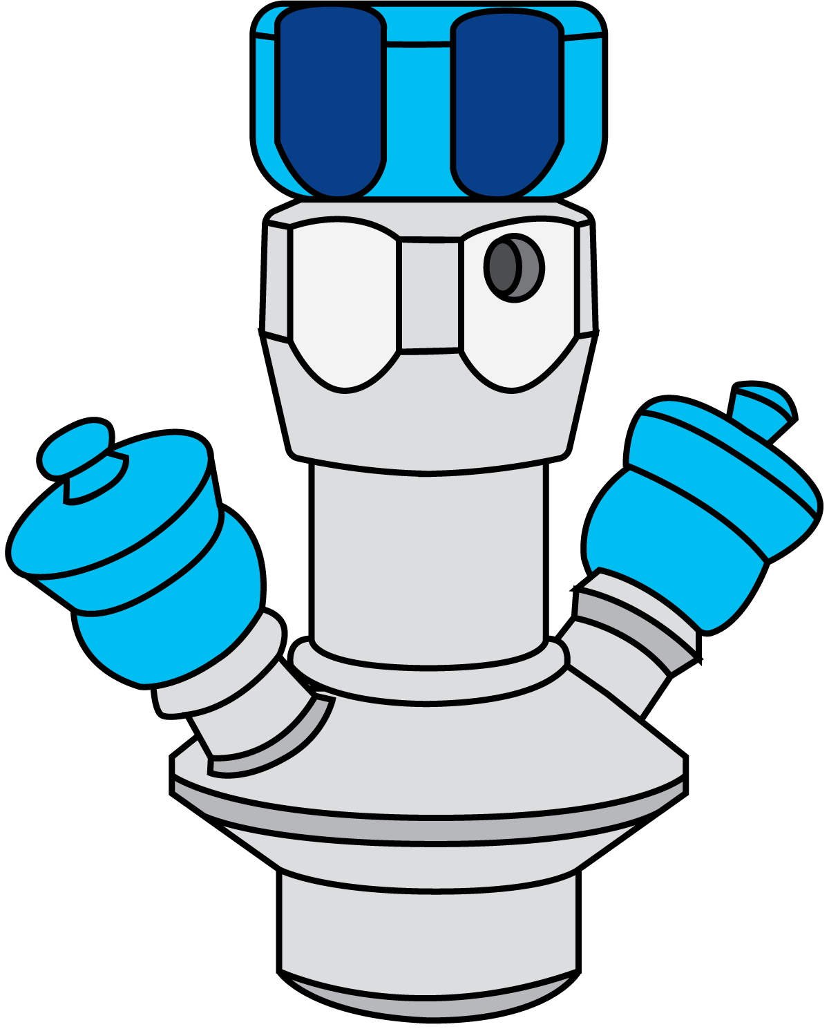
The aseptic sampling valve (Figure 7.9.5) consists of three parts, a valve body, a valve head and a membrane. The rubber membrane is placed on the stem of the valve head and works as a stretchable plug. The aseptic sampling valve is designed for sterilisation before and after each sampling.
The manual valve is opened by rotating a handle or by activating a lever. The stem and the membrane are then retracted, allowing liquid to pass.
Using the reverse procedure, the built-in spring closes the valve and keeps the channel between the hose pieces open for sterilisation.
Samples of aseptic products – heat treated at such a high temperature that they are sterile – are always collected through an aseptic sampling valve to avoid reinfection.
Valves
Mixproof valve systems
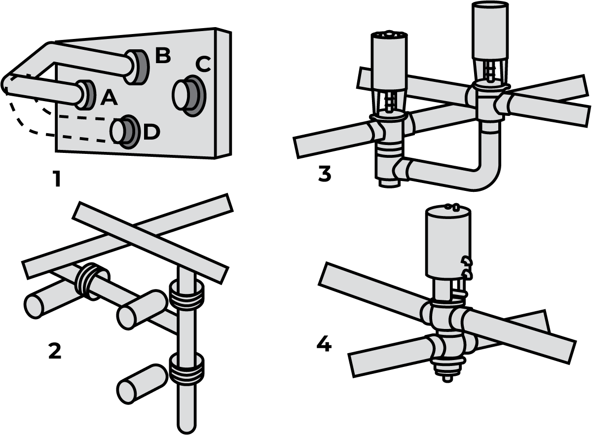
There are many junctions in a piping system where product normally flows from one line to the other, but must sometimes be closed off so that two different media can flow through the two lines without being mixed. When the lines are isolated from each other, any leakage must go to the drain without any possibility of one medium being mixed with the other.
This is a common problem faced when engineering dairy plants. Dairy products and cleaning solutions flow in separate lines and have to be kept separate. Figure 7.9.6 shows four different solutions to the same task.
Shut-off and change-over valves
There are many places in a piping system where it must be possible to stop the flow or divert it to another line. These functions are performed by valves.
Seat valves, manually or pneumatically controlled, or butterfly valves, are used for this purpose.
Seat valves
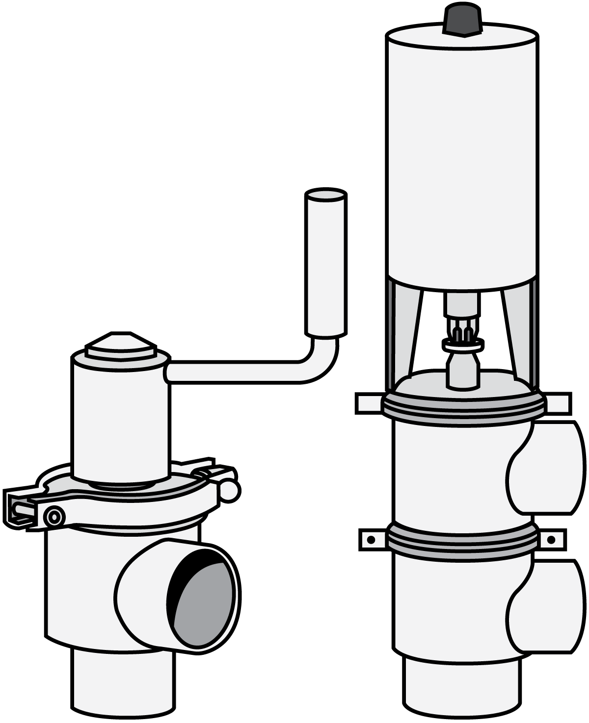
The valve body has a seat for the closing plug at the end of the stem. The plug is lifted from and lowered onto the seat by the stem, which is moved by a crank or a pneumatic actuator (Figure 7.9.7).
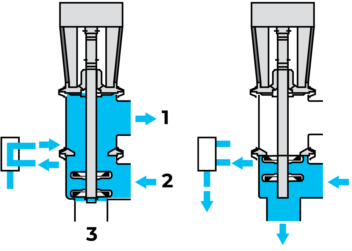
The seat valve is also available in a change-over version. This valve has three to five ports. When the plug is lowered, the liquid flows from inlet 2 to outlet 1, and when the plug is lifted to the upper seat, the flow is directed through outlet 3, as shown in Figure 7.9.8.
This type of valve can have up to five ports. The number is determined by the process requirements.
There is also another type of seat valve, where the valve plug closes in the opposite way compared to a standard valve. This valve type can be used to eliminate pressure shocks in the product lines. It can be either in a change-over or shut-off version.
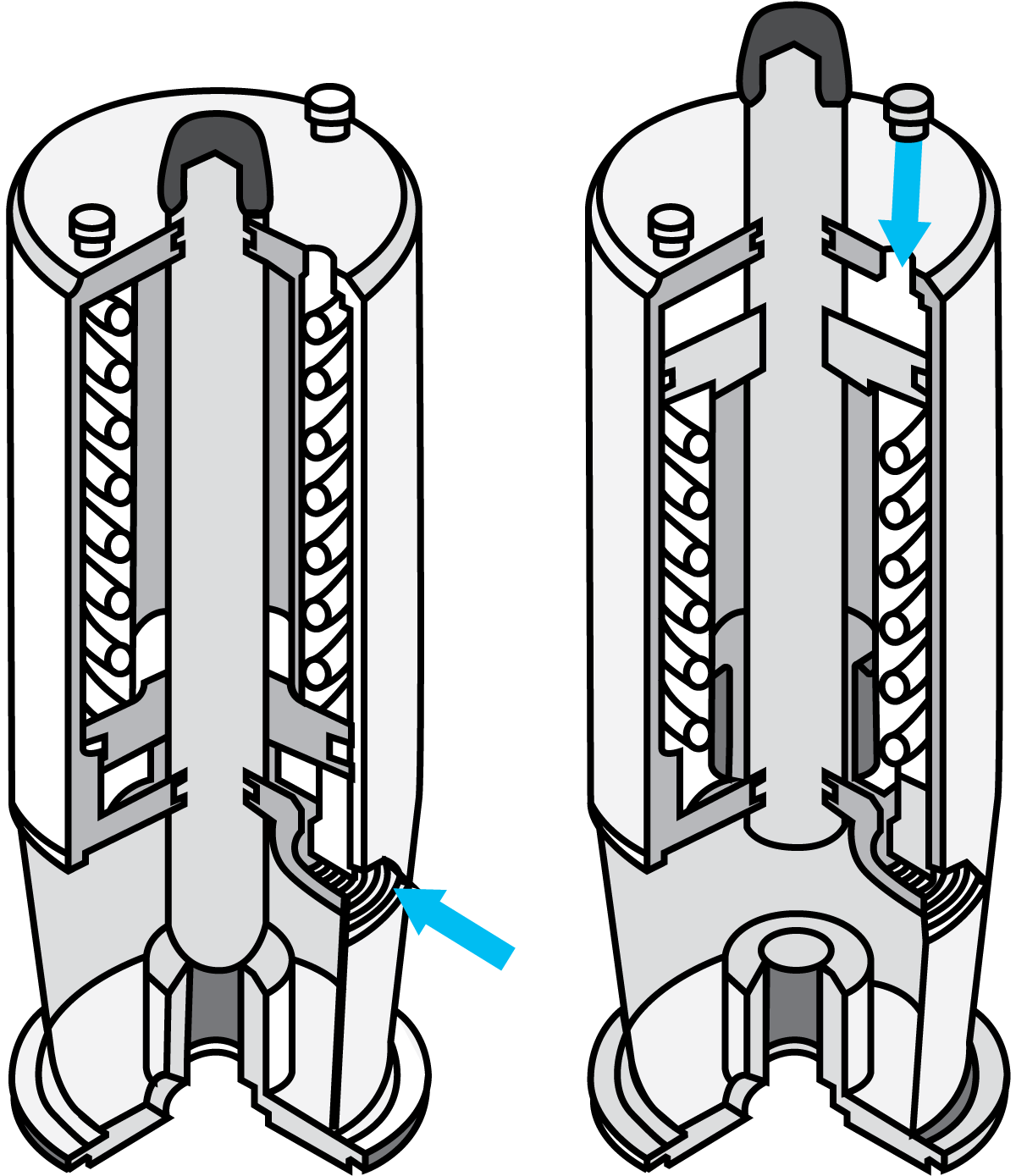
Various remote-controlled actuator alternatives are available. For example, the valve can be opened by compressed air and closed with a spring, or vice versa. It can also be both opened and closed by compressed air (Figure 7.9.9).
Actuators for an intermediate plug position and two-stage opening and closing are also available.
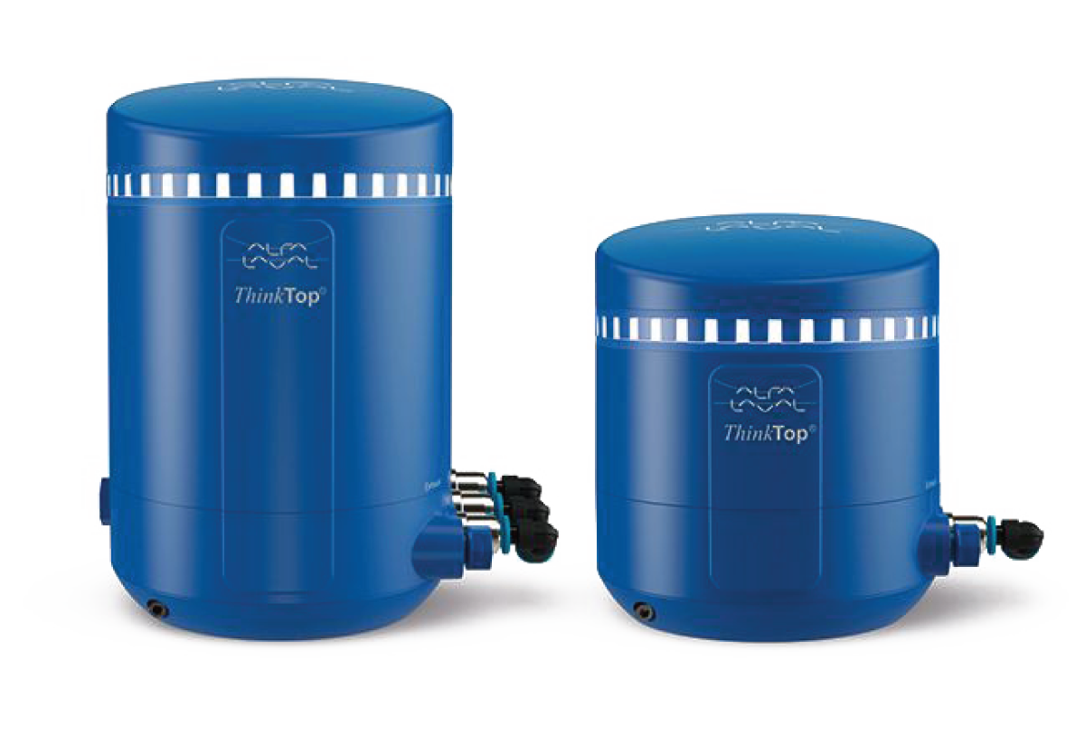
The valve control unit (Figure 7.9.10) is fitted on the top of the valve actuator. The top unit includes an indication unit, activation stem, sensor system and solenoid valves to control and supervise all kinds of pneumatic processing valves. It receives signals from a PLC to control the valve and it sends feedback signals to the PLC to indicate when the valve is in a certain position.
The top unit can easily be set by remote control and indicate seat lift of mixproof valves, and it includes a maintenance program to indicate when the plug seals of a single seat are worn out.
The modern top units can be used for IO-link, digital, as well as bus communication systems. More basic top units can be used only in digital systems for simple control and indication of open/closed valve positions.
A solenoid valve is fitted in the top unit. An electric signal triggers the solenoid valve and allows compressed air to enter the actuator. The valve then opens or closes as required. On the way, the compressed air passes through a filter to free it from oil and other foreign matter that might affect the proper operation of the valve. The air supply is cut off when the solenoid is de-energised and the air in the product valve is then evacuated through an exhaust port in the solenoid valve.
Butterfly valves
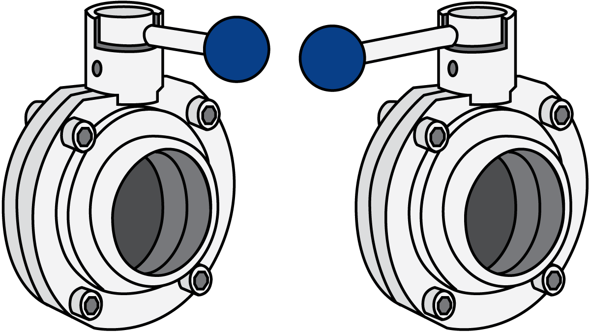
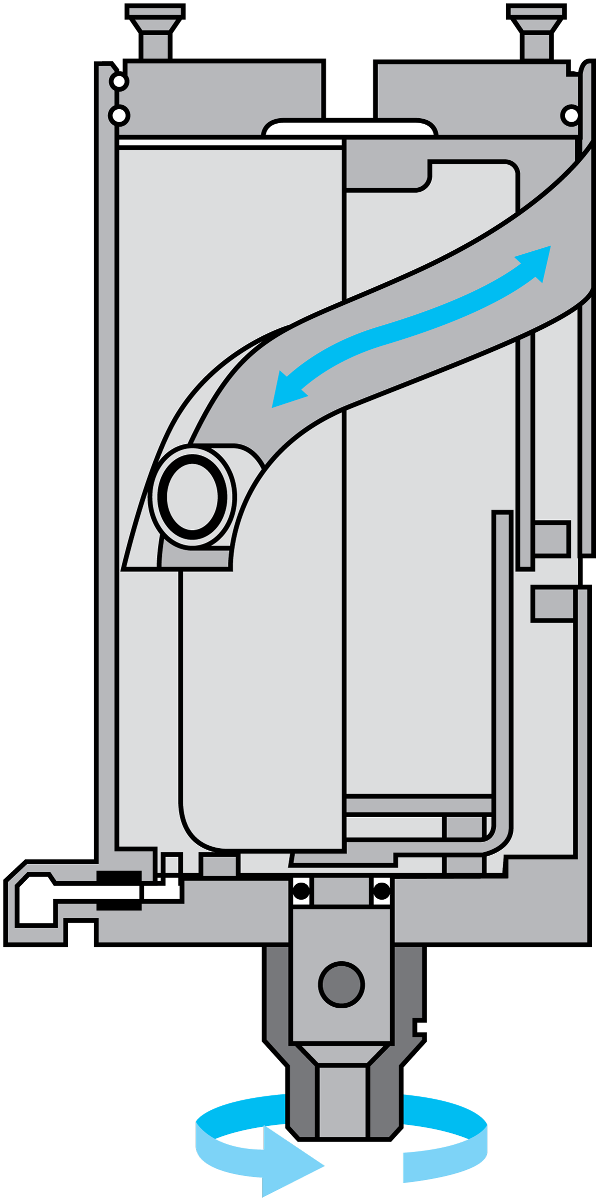
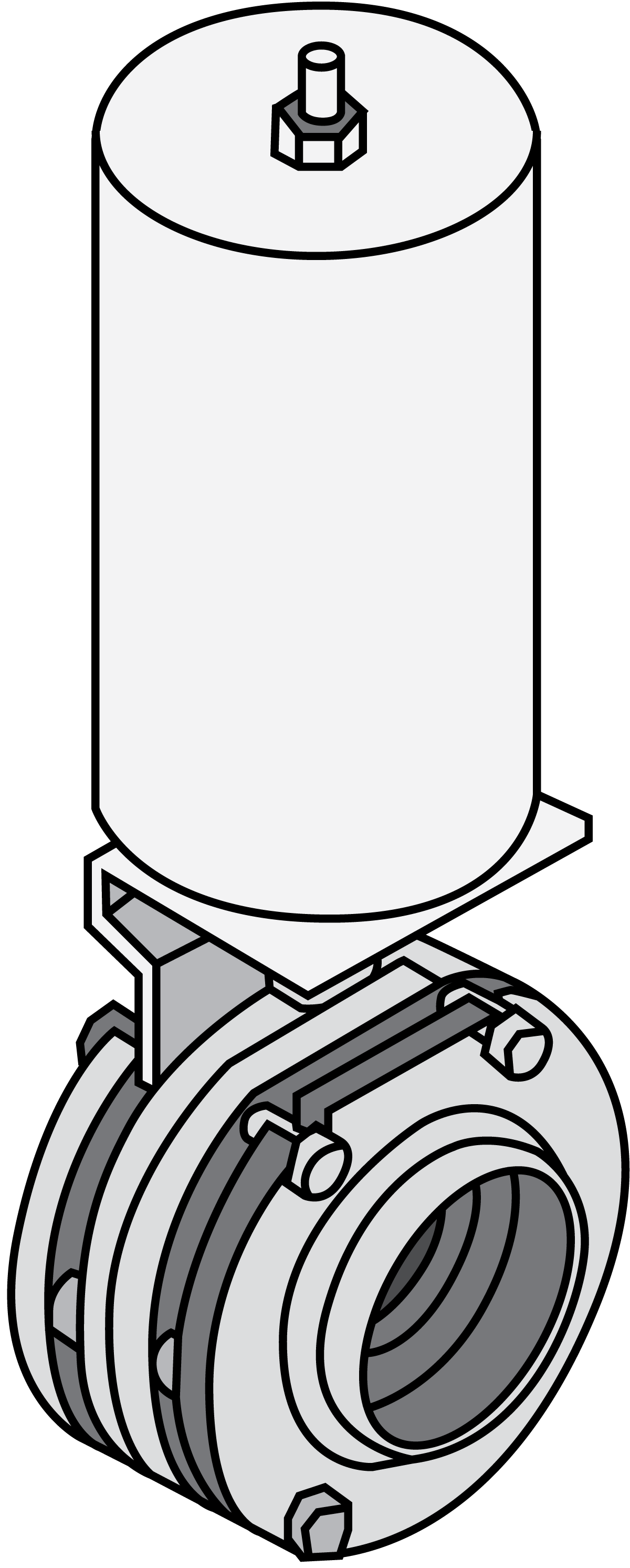
The butterfly valve (Figure 7.9.11) is a shut-off valve. Two valves must be used to obtain a change-over function.
A butterfly valve is often used for sensitive products, such as yoghurt and other cultured milk products, as the restriction through the valve is very small, resulting in a very low pressure drop and no turbulence. It is also good for high viscosities and, being a straight-through valve, can be fitted in straight pipes. The valve usually consists of two identical halves with a seal ring clamped between them. A streamlined disc is fitted in the centre of the valve. It is usually supported by bushes to prevent the stem from seizing against the valve bodies. With the disc in the open position, the valve offers very low flow resistance. In the closed position, the disc seals against the seal ring.
Manual control
The butterfly valve is fitted with a handle, usually for two positions – open and closed.
This type of valve is not very suitable as a control valve but can be used for coarse control with a special handle for infinite positions.
Automatic control
An air actuator (Figure 7.9.12) is used for automatic control of the butterfly valve.
The function can be:
- Spring closing/air opening (normally closed, NC)
- Air closing/spring opening (normally open, NO)
- Air opening and closing (A/A)
The disc is easy to turn until it touches the seal ring. Then it needs more power to compress the rubber. A normal, spring-powered actuator is strongest at the beginning when less power is required, and weaker at the end, when more power is required.
It is therefore an advantage to use actuators which are designed so that they provide the correct power at the right time.
Another type of butterfly valve is the flange valve, shown in Figure 7.9.13. It is the same type of butterfly valve as described above, but it is fitted between two flanges welded to the line. Its function is the same as an ordinary butterfly valve. During operation, it is clamped between the flanges with screws. For servicing, the screws are loosened. The valve part can then be pulled out for easy servicing.
Mixproof valves
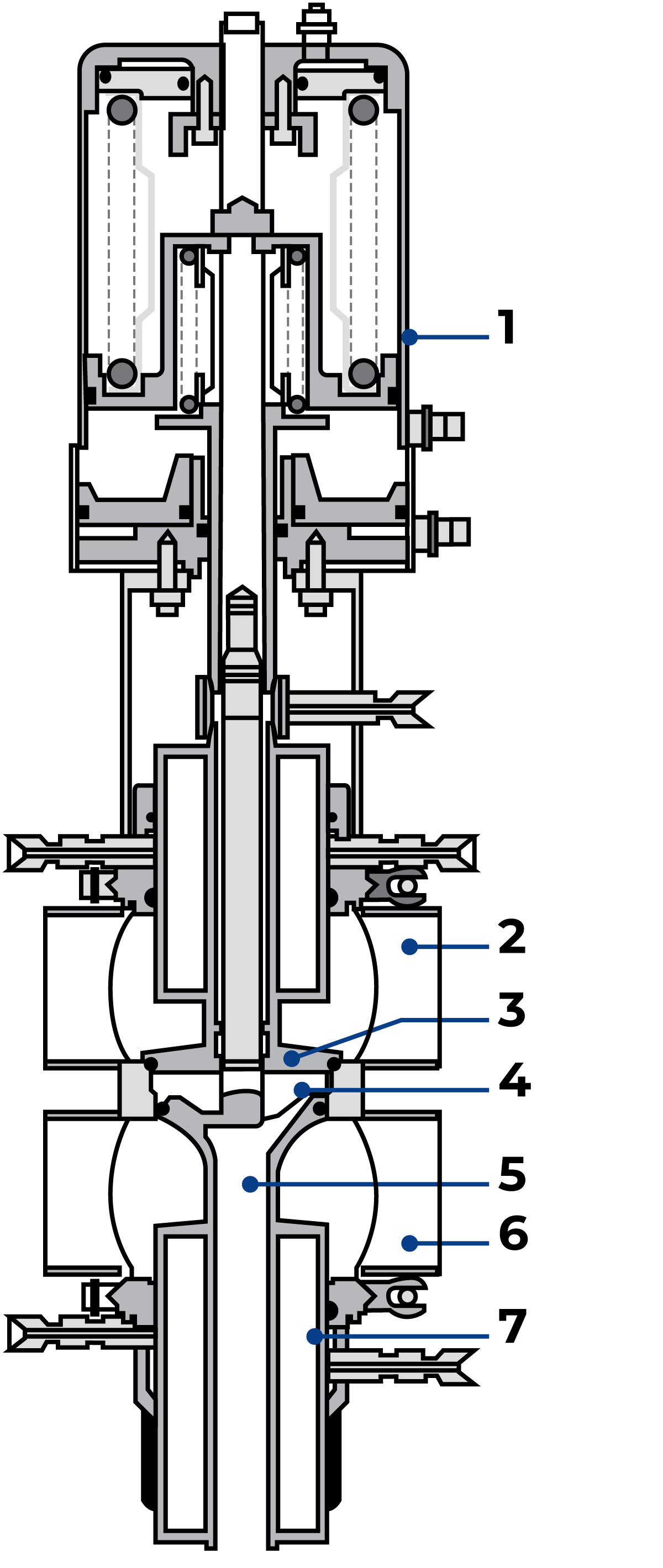
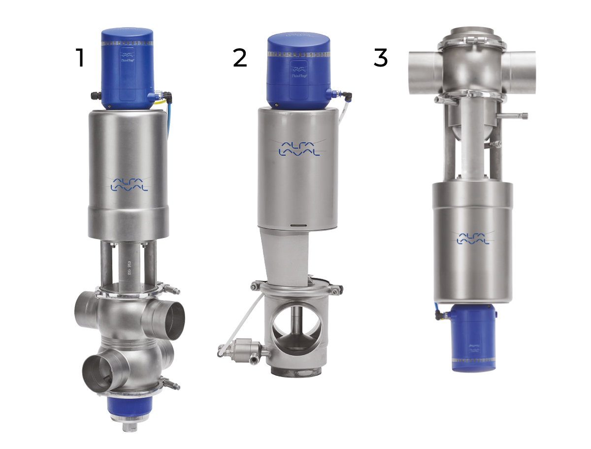
Mixproof valves (Figure 7.9.15) can be either double-seat or double-seal, but when discussing mixproof valves, it is generally the double-seat type (Figure 7.9.14) that is referred to.
A double-seated valve has two independent plug seals separating two liquids, forming a leakage chamber between them under atmospheric pressure during every working condition. In case of rare accidental leaking of product, this will flow into the leakage chamber and be discharged through the leakage detection pipe.
When the valve is open, the leakage chamber is closed. The product can then flow from one line to the other.
During cleaning, one (upper or lower) of the plugs lifts so that the seat and plug are cleaned. The cleaning liquid is discharged through the leakage chamber. External cleaning of the upper and lower plugs and leakage chamber, as well as aseptic-like operation, are also possible.
Some of the benefits of mixproof valves include cleanability, the reduction of water hammer risk, and the avoidance of spillage of product when operating the valve.
It is also possible to have a double-seated tank outlet valve. This is designed for mixproof tank outlet operation when cleaning of the line all the way to the bottom of the tank is required.
The independent seat lift of the lower plug provides easy cleaning without the need for external cleaning The tank outlet valve is compact, and the valve body can be turned at any angle to fit the piping.
Position indication and control
Position indication only
A valve can be fitted with various types of position indication (Figure 7.9.16), depending on the control system of the plant. The different types of switches are microswitches, inductive proximity switches or Hall elements. The switches are used for feedback signals to the control system.
When only switches are fitted to the valves, it is necessary to have one solenoid valve for each valve in a solenoid valve cabinet. A solenoid valve supplies compressed air to the product valve when it receives a signal and releases the air pressure when the signal disappears.
This system (1) requires one electric cable and one air hose for each valve. The combined unit (2) is a basic top unit, which is fitted on the top of the valve actuator. It includes an activation stem, sensor system and solenoid valves.
One air hose can supply many valves but one electric cable per valve is still required.
The ultimate control
This is done with a top unit shown in Figure 7.9.10, which is specially designed for computer control. The top unit includes an indication unit, activation stem, sensor system and solenoid valves.
This top unit can be used for bus communication systems, allowing only one air hose and one electrical cable to control and communicate with a large number of valves. The top unit can be programmed centrally, and the installation costs are low.
The unit includes many functions, such as remote setting, control and seat-lift indication on mixproof valves, a maintenance program for single-seat valves, and control and indication of the position of the valve plug. Some top units have software features that save water and CIP liquids in the cleaning process by flipping the seat.
Check and control valves
Check valves
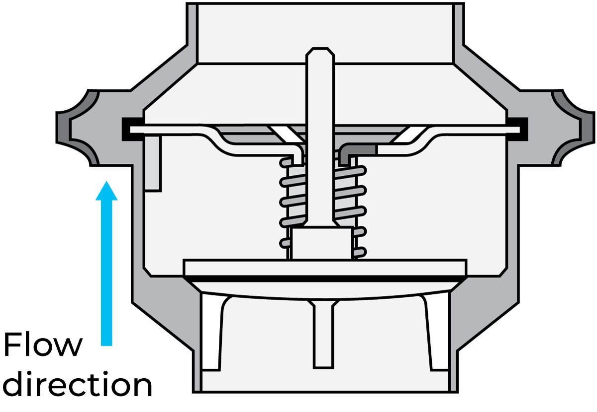
A check valve (Figure 7.9.17) is fitted when it is necessary to prevent the product from flowing in the wrong direction. The valve is kept open by the liquid flow in the correct direction. If the flow stops, the valve plug is forced against its seat by the spring. The valve then closes against the reversal of the flow.
Control valves
Shut-off and change-over valves have distinct positions, open or closed. In the regulating valve, the passage can be changed gradually. The control valve is used for accurate control of flows and pressures at various points in the system.
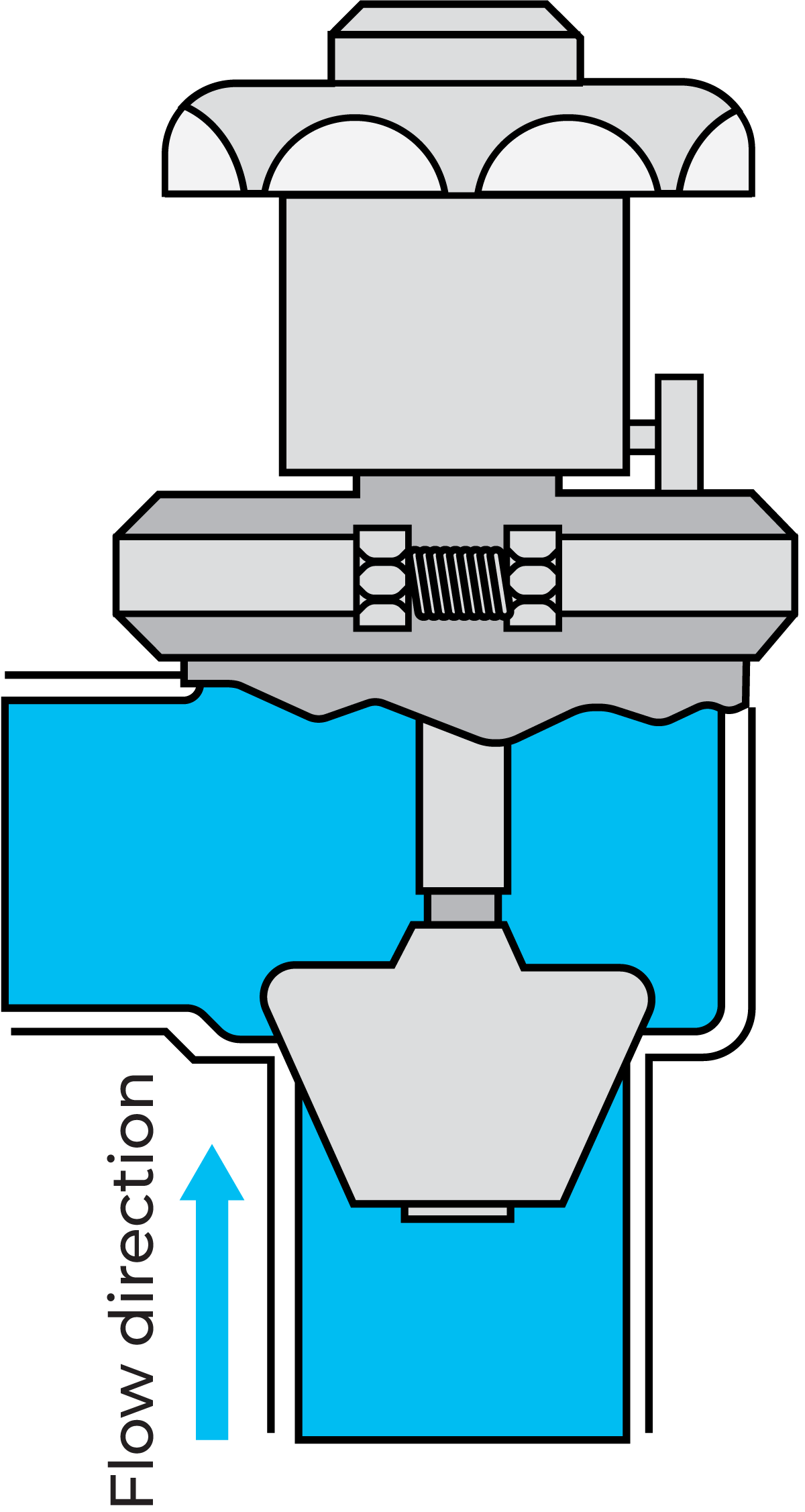
Manual control valve with variable-flow plug (Figure 7.9.18). This valve has a stem with a specially shaped plug. When the regulating handle is turned, the plug moves up or down, varying the passage and thereby the flow rate or the pressure. A scale on the valve indicates the setting.
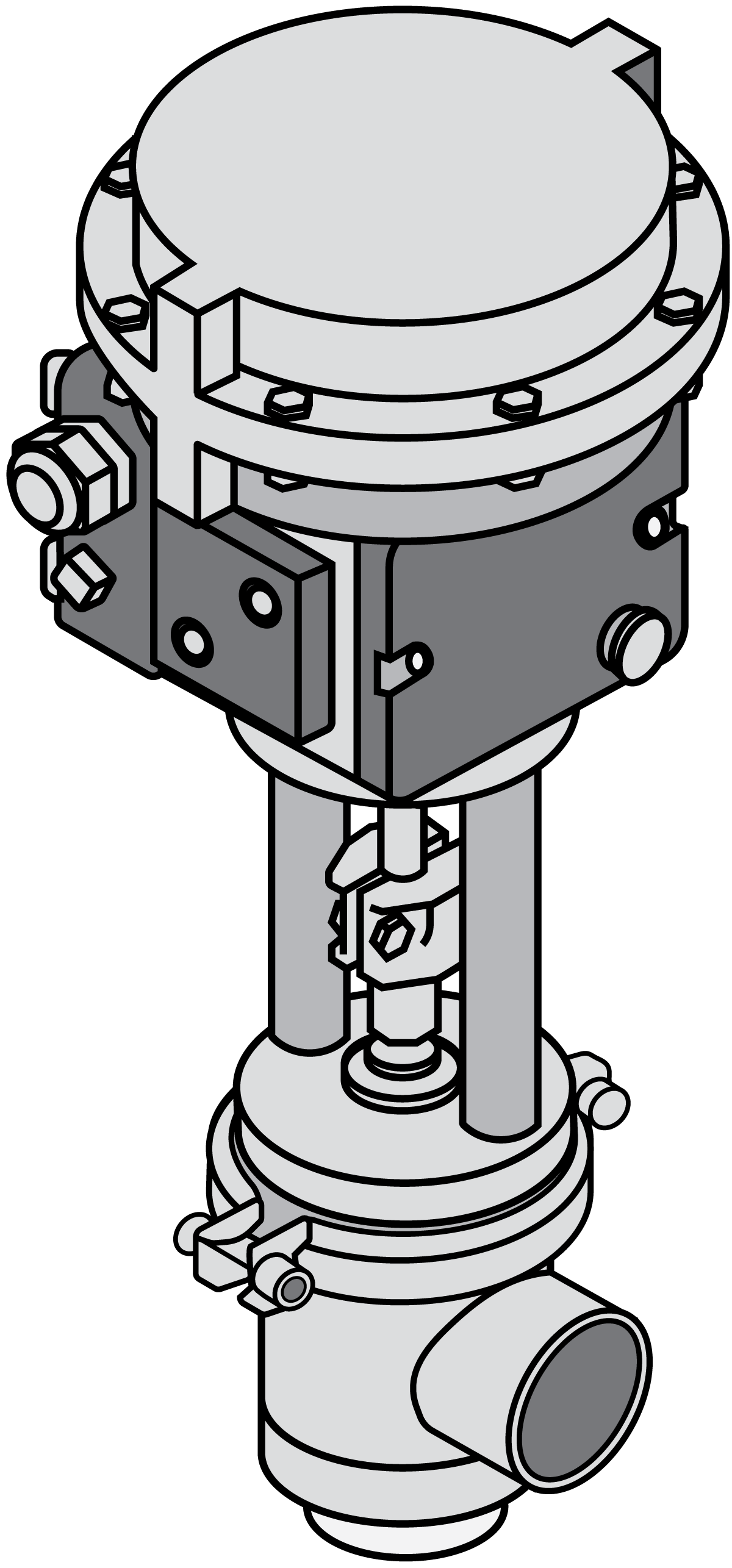
The pneumatic control valve with variable-flow plug (Figure 7.9.19) works similarly to the previously described valve. The plug-and-seat arrangement is similar to that of the manual valve. The flow is gradually throttled when the plug is lowered towards the seat. This type of valve is used for automatic control of pressures, flows and levels in processes. A transmitter is fitted in the process line and continuously transmits the measured value to a controller. This controller then adjusts the setting of the valve so that the pre-set value is maintained.
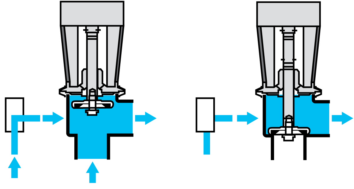
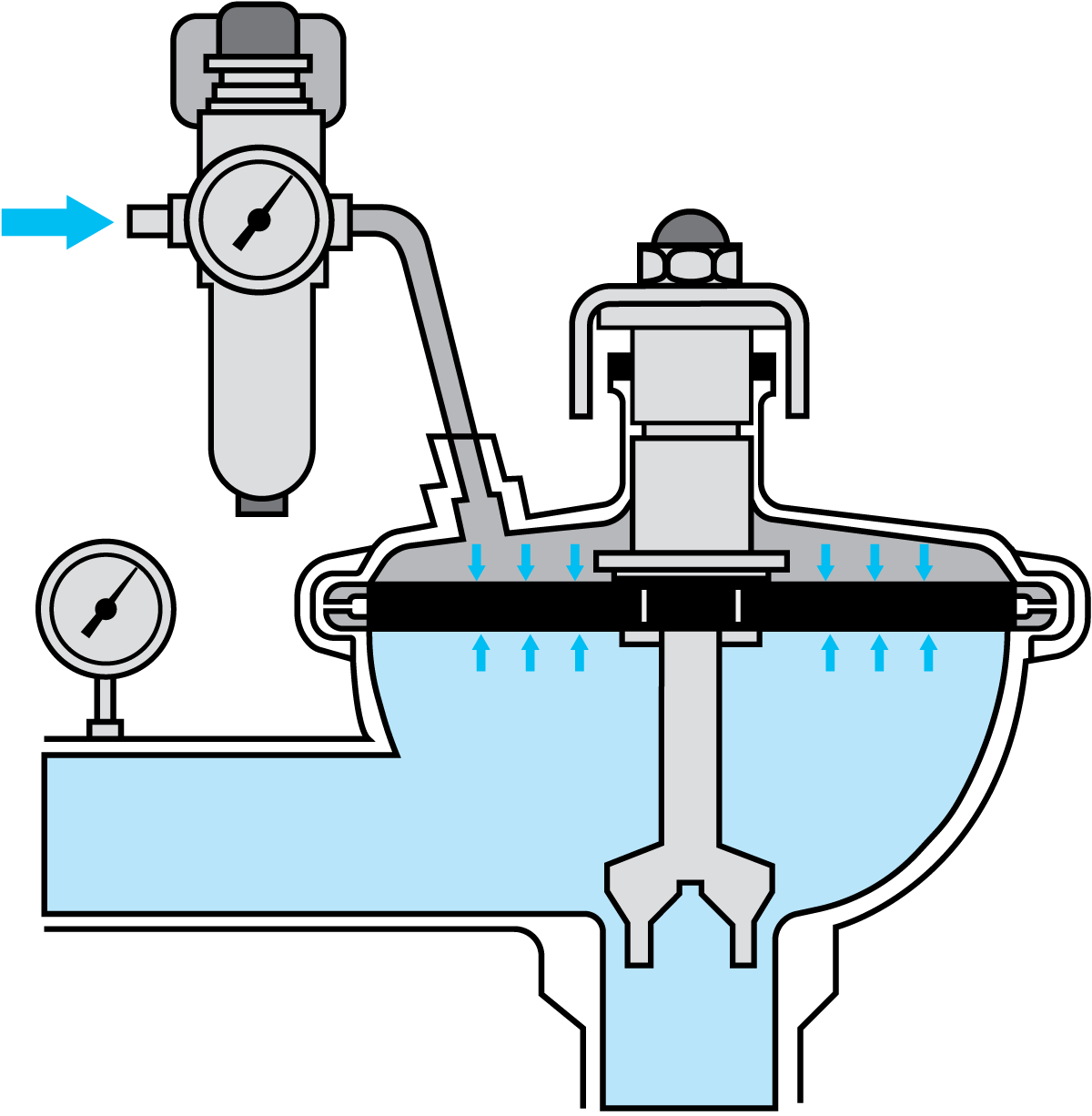
Often used is the constant-pressure valve (Figure 7.9.20). Compressed air is supplied through a reducing valve to the space above a diaphragm. The air pressure is adjusted by the reducing valve until the product pressure gauge shows the required pressure. The pre-set pressure is then maintained regardless of changes in the operating conditions. Figure 7.9.21 describes the function of the constant-pressure valve.
The valve reacts rapidly to changes in the product pressure. A reduced product pressure results in a greater force on the diaphragm from the air pressure, which remains constant. The valve plug then moves downwards with the diaphragm, the flow is reduced, and the product pressure is increased to the pre-set value.
An increased product pressure results in a force on the diaphragm that is greater than the downward force from the compressed air. The valve plug then moves upwards, increasing the passage for the product. The flow will then increase until the product pressure has dropped to the pre-set value. This valve is available in two versions for constant pressure before or after the valve.
The valve cannot control the product pressure if the available air pressure is lower than the required product pressure. In such cases, a booster can be fitted to the top of the valve. In this way, the valve can be used for product pressures up to about twice the available air pressure.
Valves for constant inlet pressure are often used after separators and pasteurizers. Those for constant outlet pressure are used before filling machines.
Overflow valves
The overflow valve is a valve used to perform pressure bypasses for safety purposes in order to protect lines, pumps, and accessories. As soon as the delivery pressure exceeds the set value, the valve opens, and the escaping medium can be discharged to the outside or returned in a controlled manner.
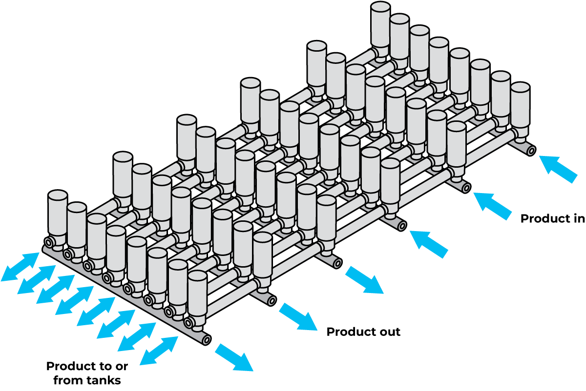
Valve systems
Valves are arranged in clusters to minimise dead ends and make it possible to distribute the product between different parts or blocks within the dairy. Valves are also used to isolate individual lines so that one line can be safely cleaned while the product is flowing in others.
Pipe supports
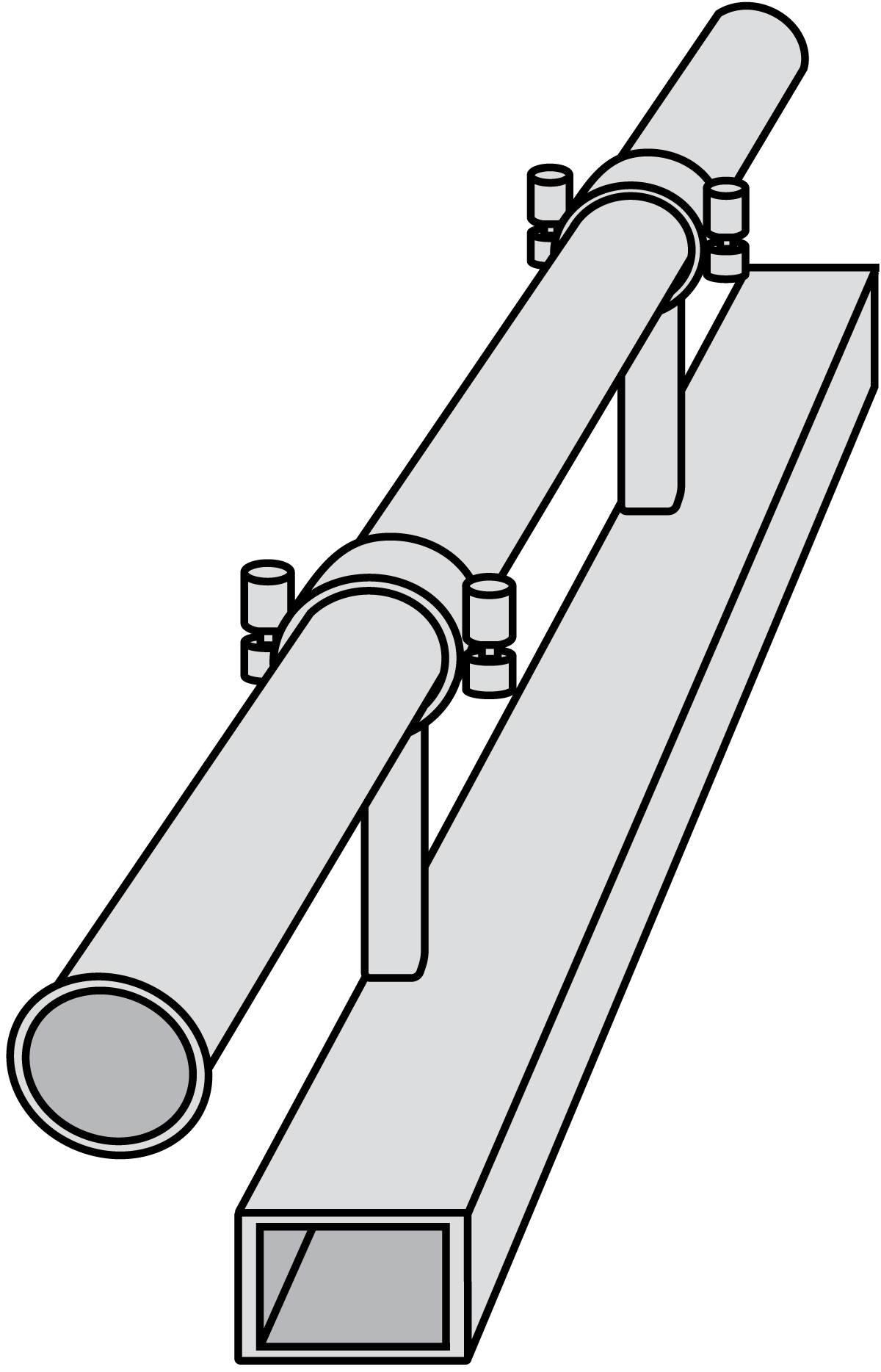
Pipes usually run about 2 – 3 metres above the dairy floor. All components must be easily accessible for inspection and maintenance. The lines should slope slightly (1:200 – 1:1000) to be self-draining. There should be no pockets at any point along the line where the product or cleaning fluid can collect.
Pipes must be firmly supported. On the other hand, the pipes should not be so restrained that movement is prevented. The pipes will expand considerably when the product temperatures are high and during cleaning. The resulting increase in length and torsional forces in bends and equipment must be absorbed. This, plus the fact that the various components make the pipe system very heavy, places great demands on accuracy and the experience of the system designer.
