Membrane technology
Membrane technology is a proven separation method used on the molecular and ionic levels. In the 1950s, huge development steps were taken regarding the permeate flux and durability of the membranes. After first being commercially introduced in water treatment plants in the early 1960s, membrane filtration was adapted for the dairy industry in the early 1970s. Membranes and membrane elements are continuously being improved in performance and durability, and the relative cost per square metre of membrane area is generally decreasing. Hence, the range of dairy applications and feasibility for membrane filtration is also continuously being extended.
Definitions
Feed
The solution which is to be concentrated or fractionated.
Permeate
The filtrate or liquid passing through the membrane.
Retentate
The concentrate or retained liquid.
Flux
The permeate flow per area of membrane, measured in litres per square metre of membrane surface area per hour [l/m2h].
Membrane fouling
The deposition and accumulation of feed components on the membrane surface and/or within the pores of the membrane, causing a flux decline during processing.
Concentration factor (CF)
The volume/mass reduction achieved by concentration, i.e. the ratio of the initial amount of feed to the final amount of retentate [CF=Feed/Retentate].
Diafiltration
A design to obtain better purification in which water is continuously added to the feed during membrane filtration to dilute the feed. Low molecular feed components that will pass through the membranes, often lactose and minerals, are hereby removed with the permeate.
Transmembrane pressure (TMP)
The pressure difference between the retentate and the permeate side of the membrane in a pressure-driven membrane system (Figure 7.4.14).
Pressure differential
ΔP is the pressure drop between the point of entry and exit in a membrane module on the retentate side of the membrane in a pressure-driven membrane system (Figures 7.4.10 and 7.4.8).
Membrane technology
In the dairy industry, membrane technology is principally associated with
- Reverse osmosis (RO) – The concentration of solutions by removal of water
- Nanofiltration (NF) – The concentration of organic components by removal of part of monovalent ions like sodium and chlorine (partial demineralisation)
- Ultrafiltration (UF) – The concentration of large particles and macromolecules such as proteins
- Microfiltration (MF) – The removal of bacteria or separation of macromolecules such as proteins
The spectrum of application of membrane separation processes in the dairy industry is shown in Figure 7.4.1.
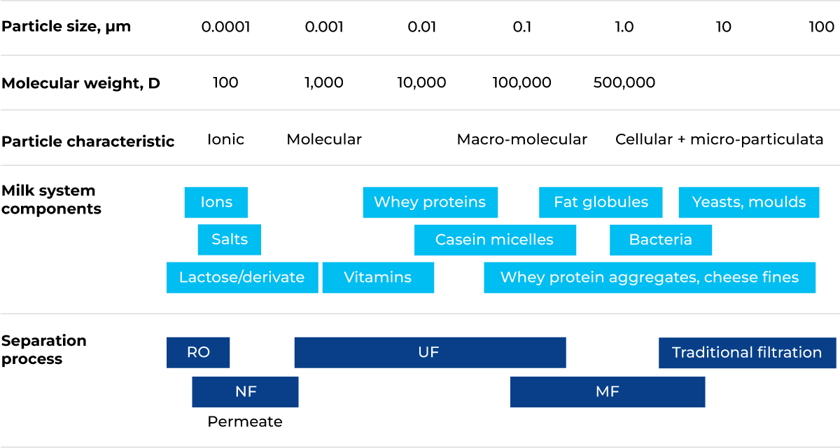
Fig. 7.4.1 Spectrum of application of membrane separation processes in the dairy industry.
All the above techniques feature pressure-driven membrane filtration processes in which the feed solution is forced through the membrane under pressure. The membranes are categorised by their salt retention (RO and NF), molecular weight cut-off (NF and UF) or nominal pore size (MF).
The cut-off is the molecular weight of the molecule that has a 90% rejection by the membrane. There is no standard method, but often sugars or polymers are used. Because of various interactions, a membrane cannot be selected purely on the basis of its salt retention, molecular weight cut-off or nominal pore size.
It should be mentioned that traditional filtration, which is operated in dead-end mode, like in a typical coffee filter, is typically used for the separation of suspended particles larger than 10 μm, while membrane filtration separates substances with molecular sizes less than 10 μm. Traditional filtration is performed in a dead-end mode, while membrane filtration is performed in both dead-end and cross-flow modes. The basic difference between traditional filtration and cross-flow membrane filtration is illustrated in Figure 7.4.2.
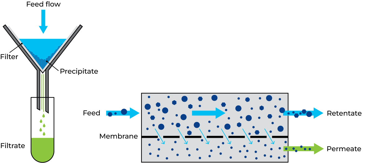
Fig. 7.4.2 Basic differences between conventional dead-end filtration and cross-flow membrane filtration.
Several differences can be noted between conventional and membrane filtration:
- Conventional filters are thick with open structures. Filter material is typically paper. Gravity is the main force affecting particle separation. Pressure may be applied only to accelerate the process. The flow of feed is perpendicular to the filter medium, and filtration can be conducted in open systems.
- Membrane filters are thin and of fairly controlled pore sizes. Nowadays, the filter material is commonly polymers, ceramics and, more rarely, cellulose acetate.
In membrane filtration, the use of a pressure difference across the membrane, a transmembrane pressure (TMP), is an essential driving force for separation. In order to create this pressure without compressing the product onto the membrane surface, cross-flow is used when creating the plant design. The feed solution flows parallel to the membrane surface at high speed on the retentate side. This speed creates friction, the liquid loses velocity as it flows towards the end of the membrane and this in turn creates a pressure differential. The permeate side has almost no pressure. With this, there is a difference in pressure across the membrane and the permeate flows perpendicular to the membrane surface. The filtration must be carried out in a closed system.
Principles of membrane separation
The membrane separation techniques utilised in the dairy industry serve different purposes (Figure 7.4.3):
RO
Typically used for dehydration of milk, whey, UF permeate and condensate.
NF
Typically used when partial desalination of milk, whey, UF permeate or retentate is required, and for the recovery of CIP chemicals. Can also be used for obtaining extraordinarily high dehydration that is not possible with RO.
UF
Typically used for the concentration of proteins in milk and whey and for protein standardization of milk intended for cheese concentration, Greek yoghurt, lactose-free milk and other dairy products.
MF
Mostly used for the reduction of bacteria in skim milk, whey and brine, but also for defatting whey intended for Whey Protein Isolate (WPI) and for milk protein fractionation to produce native milk serum protein and micellar casein concentrate.
Filtration modules
The filtration modules used may be of different configurations.
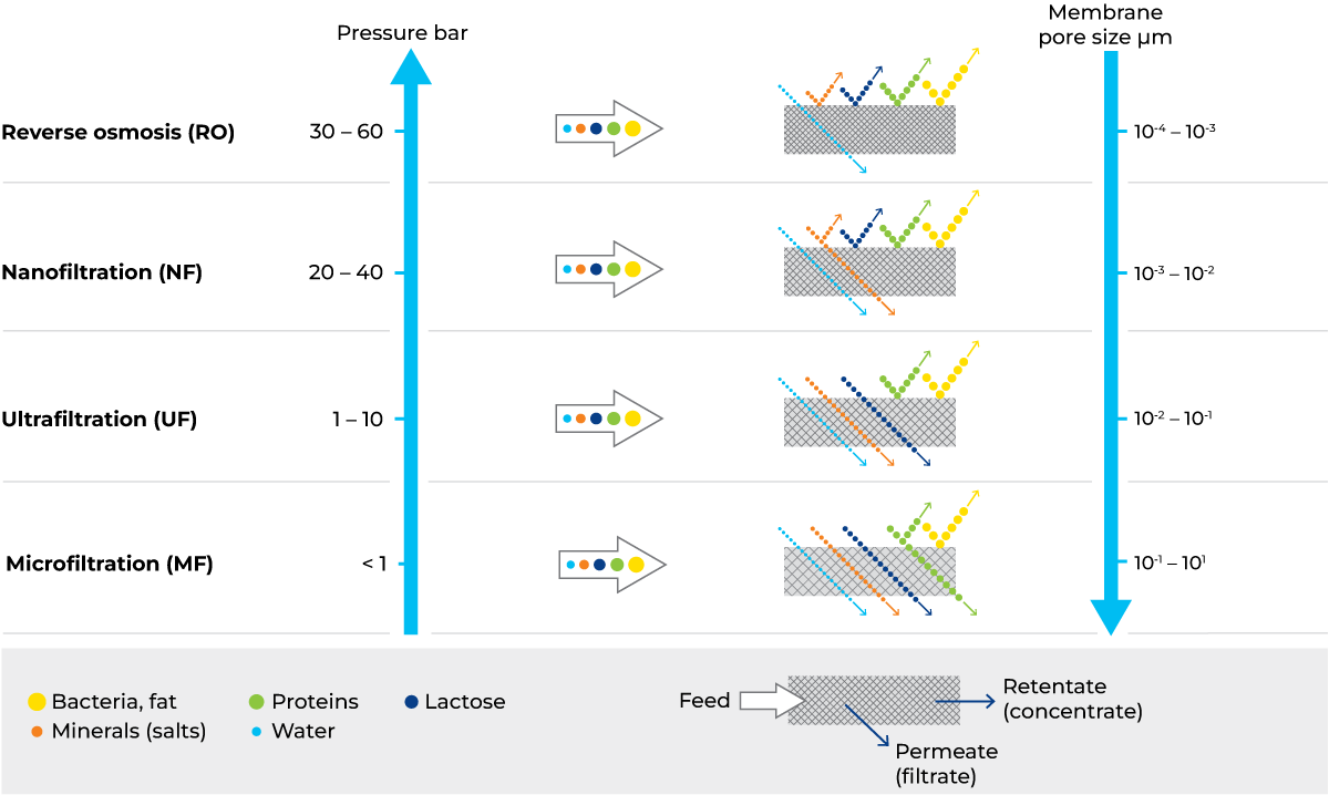
Fig. 7.4.3 Principles of membrane filtration.
Spiral-wound design
A spiral-wound element contains one or more membrane envelopes, each of which contains two layers of membrane separated by a porous permeate material. This material, called the permeate channel spacer, allows the permeate passing through the membrane to flow freely. The two layers of membrane with the permeate channel spacer between them are sealed with adhesive at two edges and on one end to form the membrane envelope. The open end of the envelope is connected and sealed to a perforated permeate-collecting tube. The envelope configuration is illustrated in Figures 7.4.4 and 7.4.5.
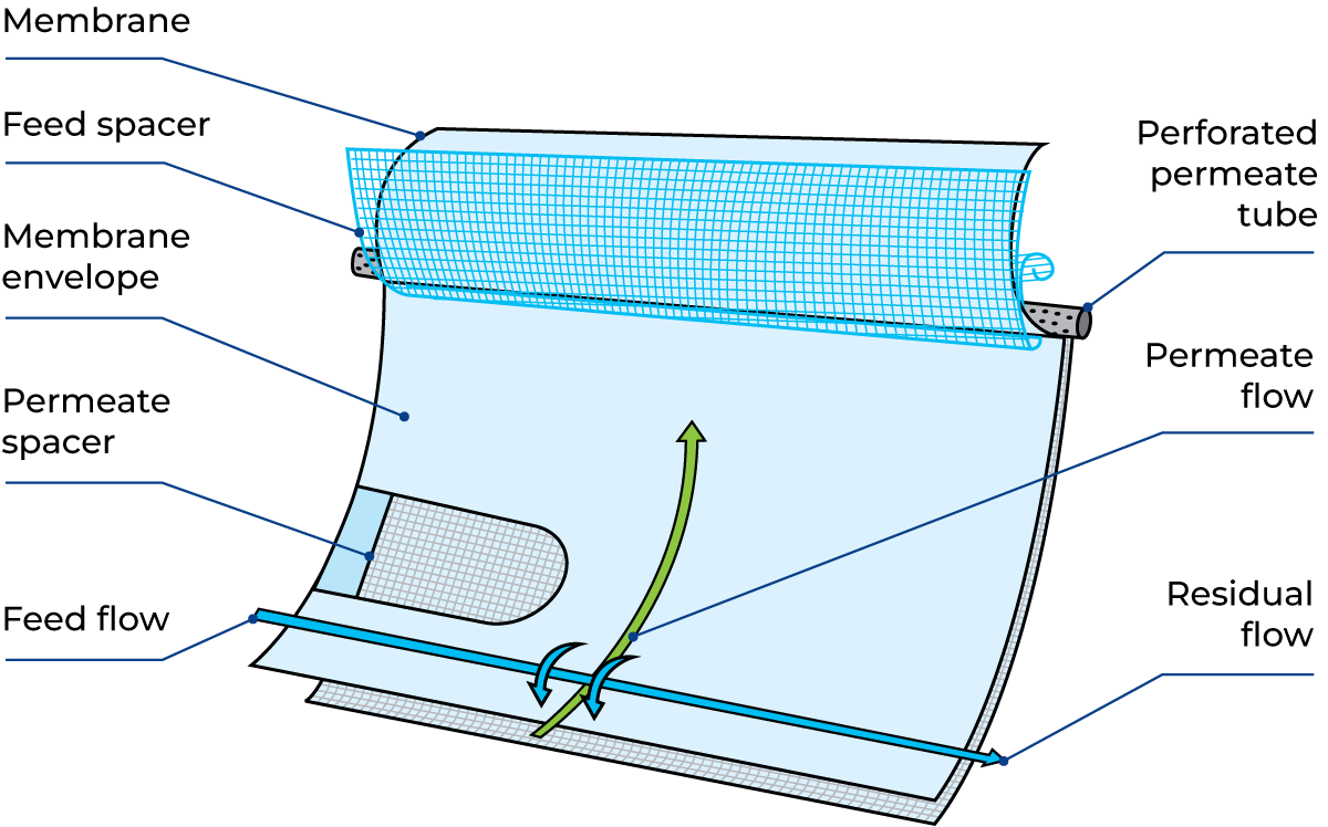
Fig. 7.4.4 Envelope formation of the spiral-wound filter design.
A plastic mesh with a diamond parallel design, known as the feed spacer, serves as a channel for the flow of feed solution through the system and is placed in contact with one side of each membrane envelope. Due to the mesh design, the feed spacers also act as turbulence generators, optimising the flow conditions at the membrane surface during production and cleaning, which helps to keep the fouling and concentration polarisation under control.
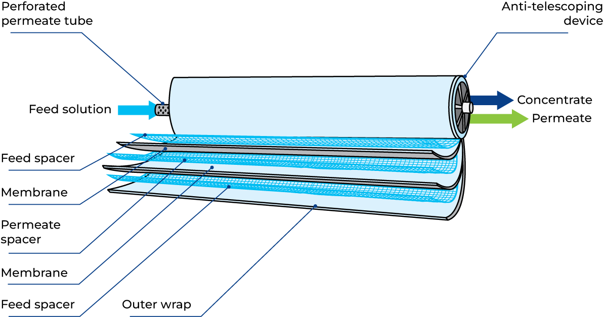
Fig. 7.4.5 Spiral-wound membrane with the anti-telescoping device.
The entire assembly is then wrapped around the perforated permeate-collecting tube to form the spiral-wound membrane. Spiral-wound membranes are equipped with an anti-telescoping device (ATD) (Figure 7.4.5) between the downstream ends of the membrane elements to prevent the velocity of treated fluid from causing the layers to slip.
Several elements – normally up to six – can be connected in series inside the same stainless steel module as shown in Figure 7.4.6. Membrane and permeate spacer material: polymer.
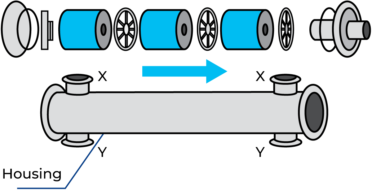
Fig. 7.4.6 Spiral-wound module assembly.
Either or both of the pairs of connecting branches (X and Y) can be used for stackable housing, specially used in UF concepts.
Plate and frame design
This system consists of membranes, typically polymers, sandwiched between membrane support plates, which are arranged in stacks, similar to ordinary plate heat exchangers. The feed material is forced through very narrow channels that may be configured for parallel flow or as a combination of parallel and serial channels. A typical design is shown in Figure 7.4.12.
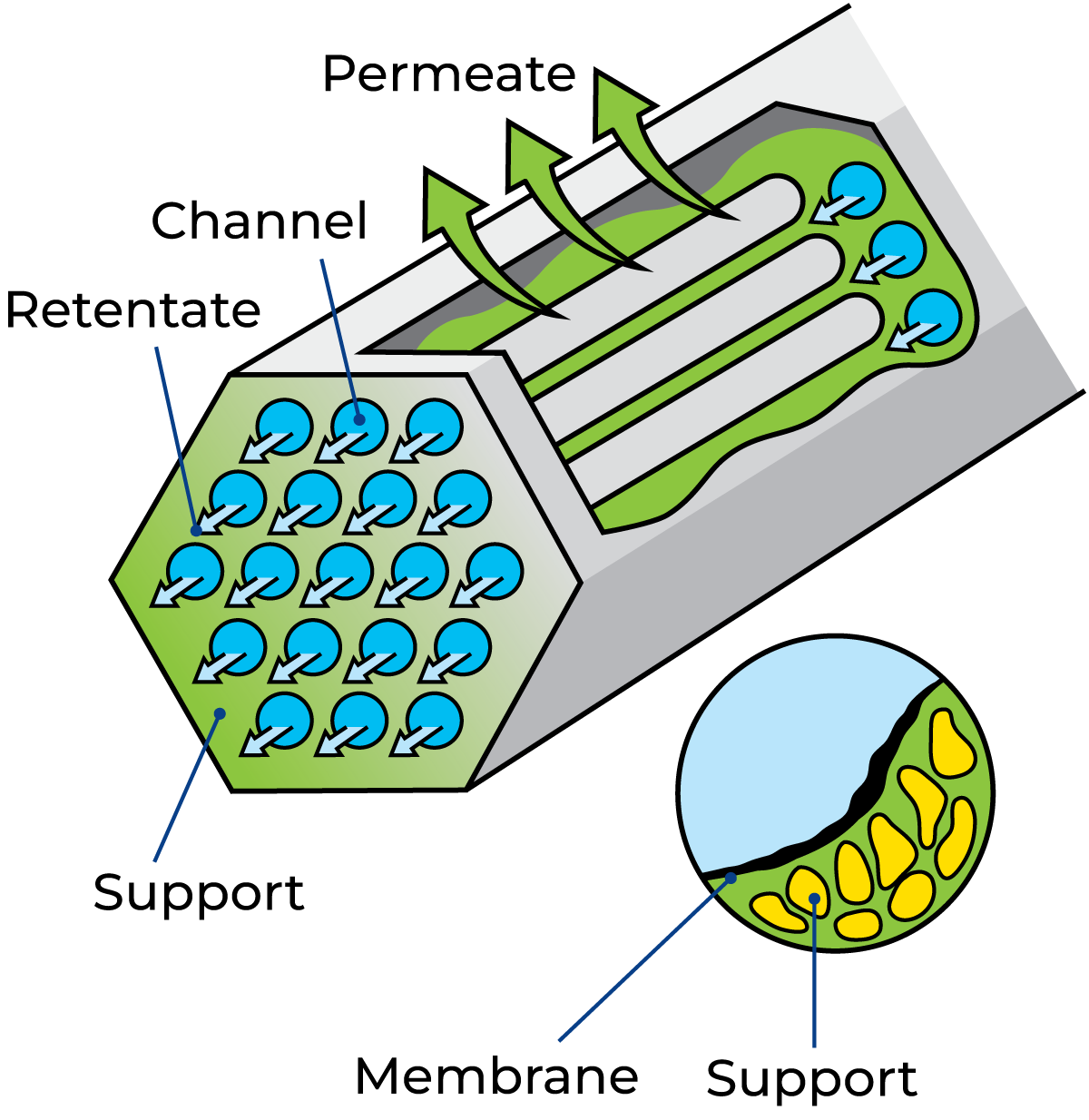
Fig. 7.4.7 Cross-flow filtration in a multichannel element (19 channels).
A module is usually divided into sections, and in each of these, the flow between pairs of membranes is in parallel. The sections are separated by a special membrane support plate in which one hole is closed with a stop disc to reverse the direction of flow, resulting in serial flow between successive sections. Modules are available in various sizes.
The system is capable of handling high viscosities and is applied in the application of, for example, cream cheese, Skyr and other high-viscous dairy products.
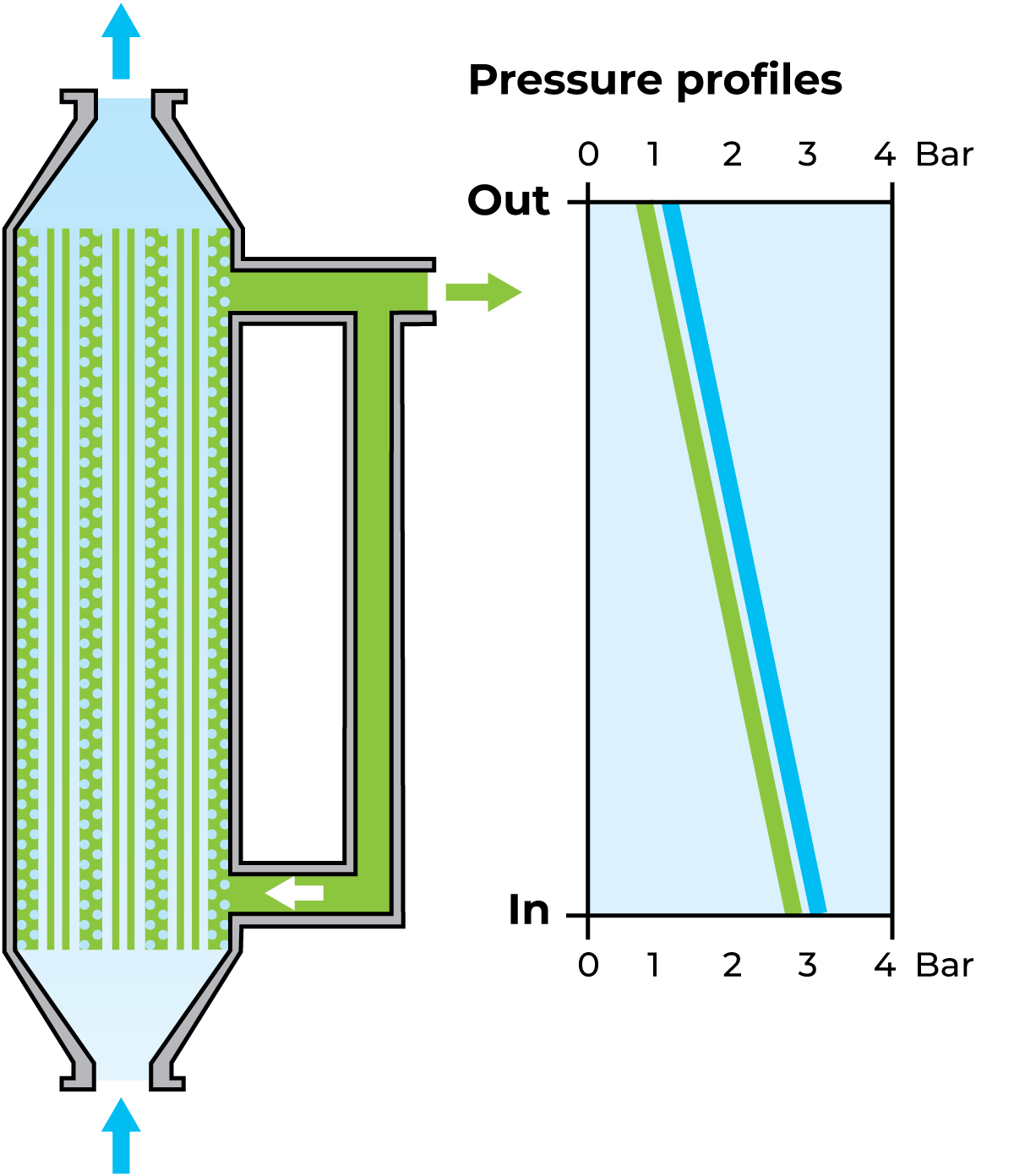
Fig. 7.4.8 Pressure drop at the uniform transmembrane pressure system.
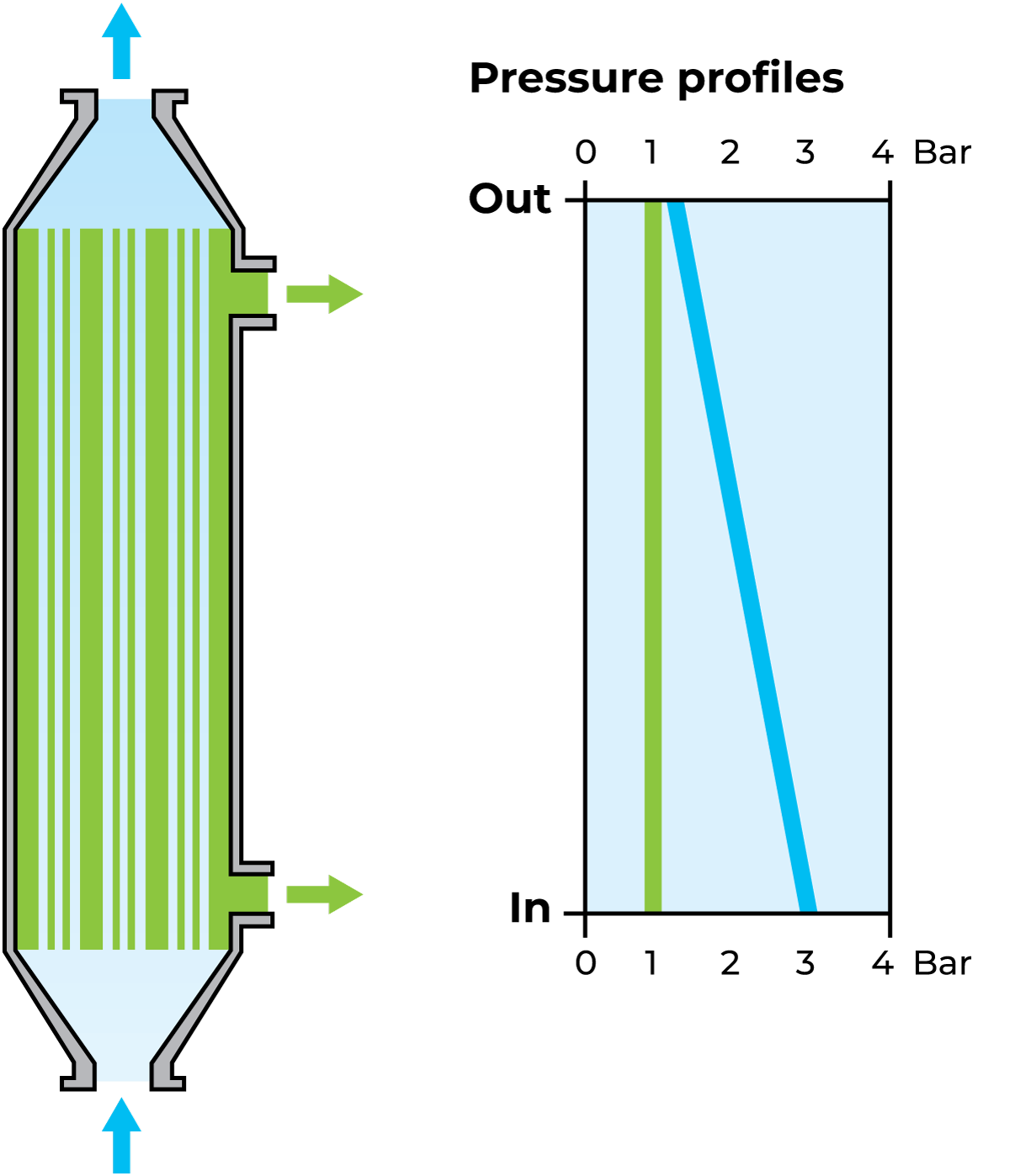
Fig. 7.4.10 Pressure drop during conventional cross-flow microfiltration.
Tubular ceramic design
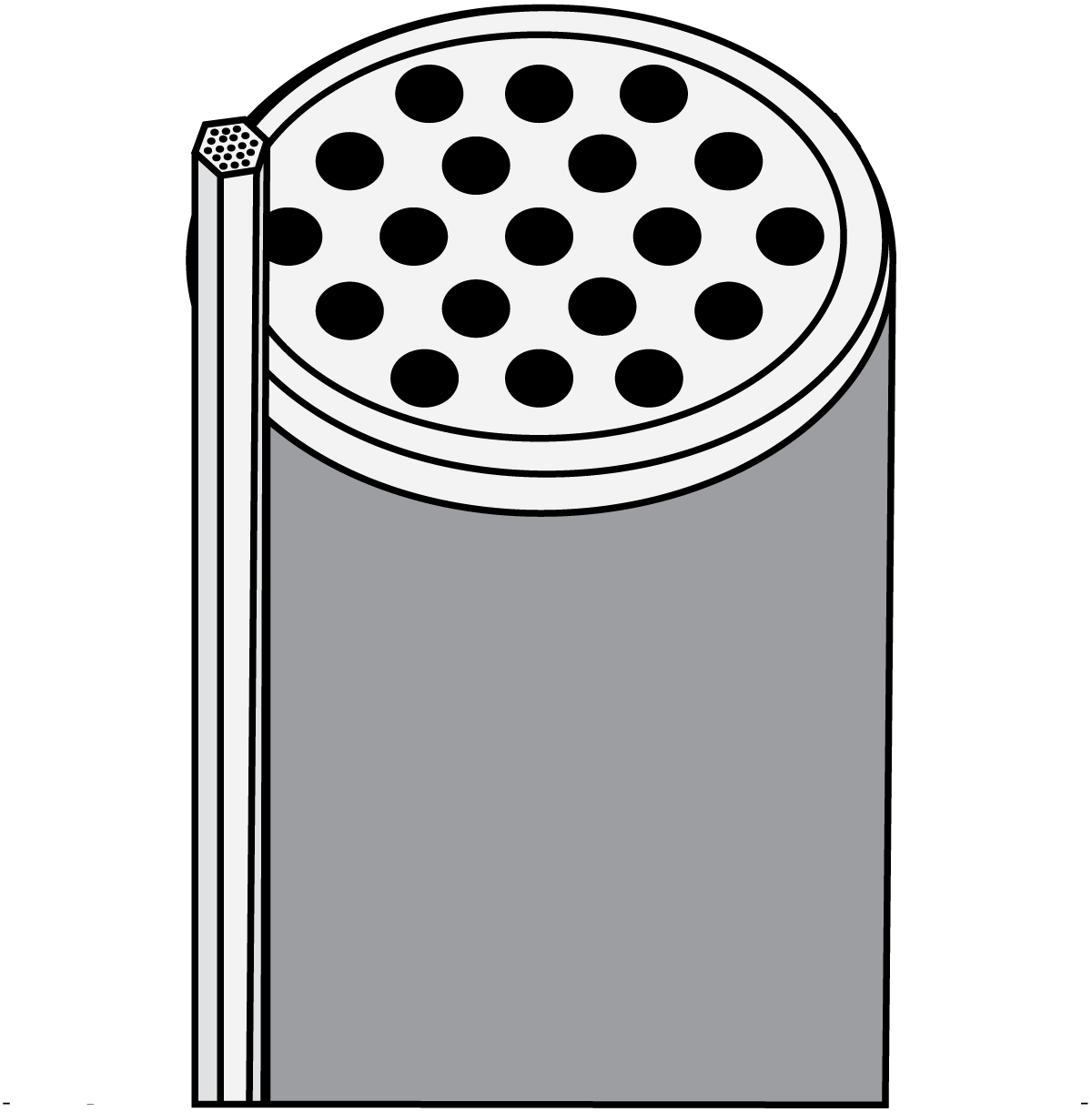
Fig. 7.4.9 The membrane elements
1, 7 or 19 (shown) in parallel are installed in a stainless steel module.
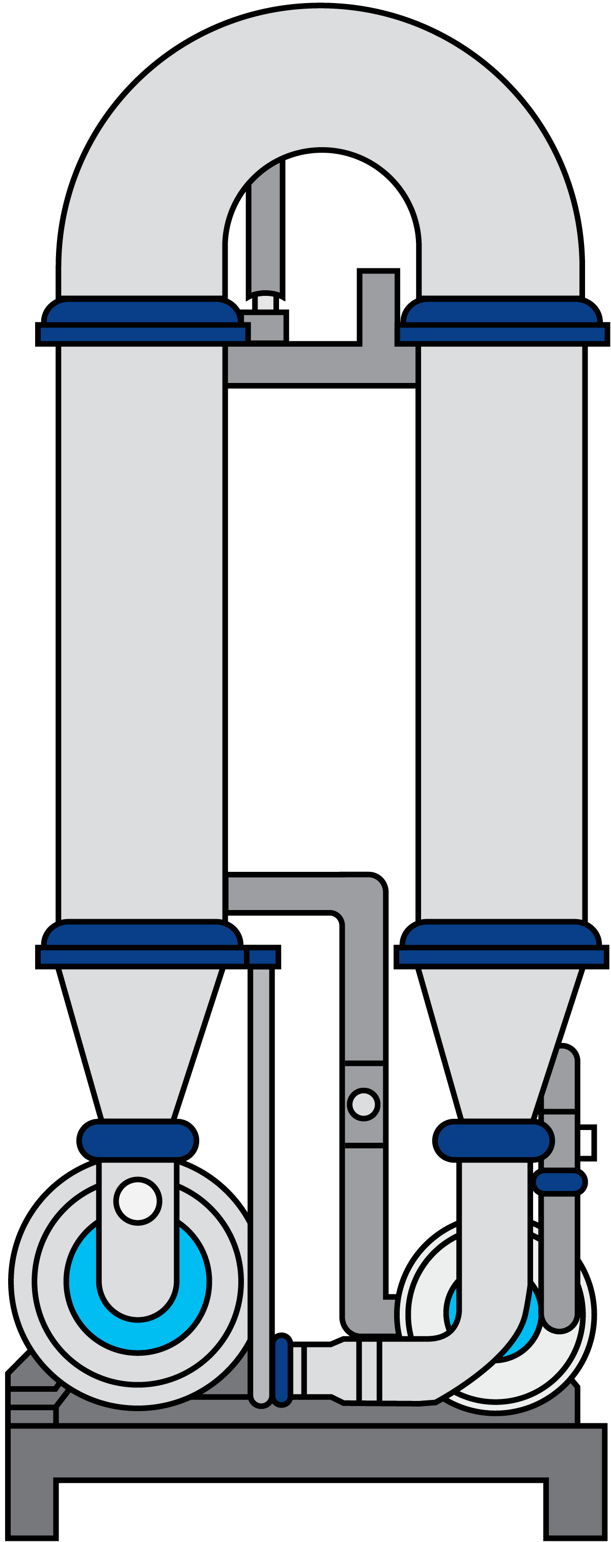
Fig. 7.4.11 An industrial membrane filter loop
Consists of:
- two filter modules connected in series
- one retentate circulation pump
- one permeate circulation pump
A tubular concept with ceramic membranes is available in the dairy industry, especially in systems for the reduction of bacteria in milk, whey and WPC, but also for applications in milk fractionation and production of Greek yoghurt.
The filter element (Figure 7.4.7) is an example of a ceramic membrane element. The thin walls of the channels are made of fine-grained ceramic and constitute the membrane. The support material is coarse-grained ceramic.
A number of membrane elements are installed in a module. Figure 7.4.9 shows a module with membrane elements, one of which is exposed to the left of the module. For industrial purposes, several modules are put together in series, forming a loop with a circulation pump (Figure 7.4.11 ). Depending on the required capacity, a number of loops can be installed in parallel or in series.
The feed is pumped into the modules from below at a high flow rate. The high flow rate causes a high pressure difference (ΔP) along the membrane elements, which leads to an uneven TMP as the TMP is higher at the inlet than at the outlet. The very high TMP at the inlet quickly causes fouling of the membrane. This phenomenon is illustrated in Figure 7.4.10 , which shows cross-flow microfiltration. Experience shows that a low TMP gives much better performance, but in cross-flow microfiltration, a low TMP only occurs at the outlet, i.e. on a very small part of the membrane area.
A unique uniform transmembrane pressure (UTP) system has been introduced to achieve optimum conditions in the entire area. The system, illustrated in Figure 7.4.8, involves high-velocity permeate circulating concurrently with the retentate, creating a pressure drop on the permeate side which is equal to the ΔP on the retentate side. This gives a uniform TMP over the whole of the membrane area, and thus optimum utilisation of the membrane. The UTP system is possible because normally the space between the elements inside the module, i.e. on the permeate side, is empty, but in the UTP version, it is filled with plastic grains. The pressure drop on the permeate side is regulated by the permeate pump and is constant during operation of the plant.
Today, specially designed membrane elements are available that have this UTP system built into their structure. When using this type of membrane, there is no need for circulation on the permeate side. These membranes are called gradient pressure (GP) membranes and have a flow resistance which differs along the element.
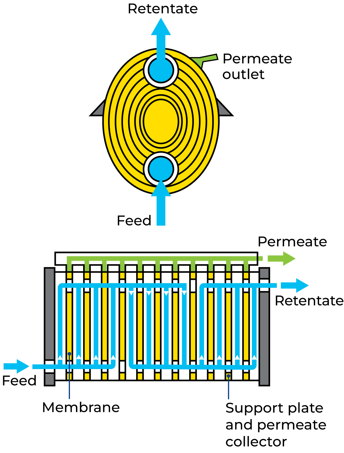
Fig. 7.4.12 Example of a plate and frame system (Alfa Laval) for UF.
Separation characteristics for membranes
The separation characteristic of a membrane is determined by many different factors related to the membrane material, membrane manufacturing, shape and flexibility of molecules, and the flow dynamic and transport mechanisms at the membrane surface. For the membrane manufacturers to be able to characterise the membrane performance, several methods have been developed to determine the separation characteristics of the specific membrane type. One example is UF membranes that can have a definite or a diffuse separation characteristic, as illustrated in Figure 7.4.13, for two UF membranes with the same molecular weight cut-off. The phenomenon occurs when the pore size distribution of the membrane is narrow or wide, and if it results in a different rejection curve slope.
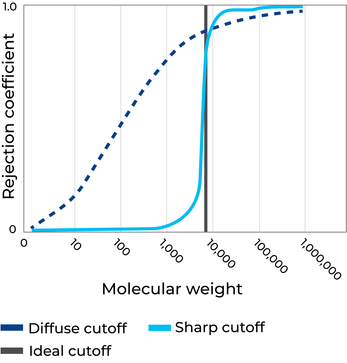
Fig. 7.4.13 Typical rejection characteristics of two ultrafiltration membranes with the same molecular weight cut-off (10kDa), showing ideal, sharp and diffuse separation characteristics.
Membranes with a narrow pore size distribution let everything with a definite lower molecular weight permeate, while membranes with a wide pore size distribution let some material with a higher molecular weight permeate and reject some with a lower molecular weight, although the two membranes are defined as having the same molecular weight cut-off.
Due to potential variations in pore shape, the molecular weight cut-off should be considered with caution when determining separation characteristics. Another influential factor is the shape of the separated molecules. An ideal hard spherical molecule cannot be compared to a flexible or shaped molecule.
In addition, there is a multi-variant dependency of separation characteristics that makes applying membrane filtration in the dairy industry very complex, but also offers the possibility of being unique, because when a system is designed and set up with all the relevant parameters, the membrane is just a single parameter. Therefore, being able to reliably reproduce a product requires more than just knowing the membrane cut-off – the total set of parameters has to be known and under control.
Material transport through the membrane
Separation capacity depends on a number of factors:
- Membrane resistance, which is characteristic for each membrane and is determined by: membrane thickness, surface porosity, and pore diameter.
- Transport resistance, i.e. the concentration, polarisation and fouling effects are phenomena that occur at the surface or in the porous structure of the membranes during the filtration process.
The formation of a layer that increases resistance can be explained as follows:
- Large molecules (i.e. protein and fat) are transported by convection to the membrane at right angles to the direction of flow. Due to retention, the concentration of molecules will accumulate at the membrane surface.
- A concentration gradient produces a back diffusion in the opposite direction.
- Parallel to the membrane, the proteins present in the layer close to the membrane surface move at velocities that vary according to the increase in axial flow rate.
- The fouling effect is not uniformly distributed along the membrane, especially when the ΔP gives different TMPs along the membrane surface. The upstream end of the membrane thus clogs first and the fouling gradually spreads over the whole surface, reducing capacity and eventually making it necessary to stop and clean the plant.
- The main effect of fouling is that the removal of permeate decreases as filtration proceeds.
Pressure conditions
Pressure is the driving force of filtration, and an important distinction must be made between:
1. The delta pressure drop (ΔP = P1 – P2) along the module.
The higher the velocity through the module, the higher the value of ΔP. A higher velocity results in a higher shear at the membrane surface and a lower polarisation effect. However, there are constraints such as the membrane's resistance to pressure and the price of pumps capable of delivering both high flows and high pressure.
2. TMP is the pressure drop between the retentate and the permeate sides of the membrane at a particular point along the membrane. The main criterion of a membrane system's efficiency is expressed as the flux – the flow per membrane area and hour [l/m2h] – and is a function of TMP.
The TMP, i.e. the force pushing the permeate through the membrane, is greatest at the inlet and lowest at the discharge end of the module. Since the decrease in TMP is linear, an average TMP is given by:
ΔP over the membrane (P2 – P1) and the transmembrane pressure profile (P1+P2/2-P3) are illustrated in Figure 7.4.14.
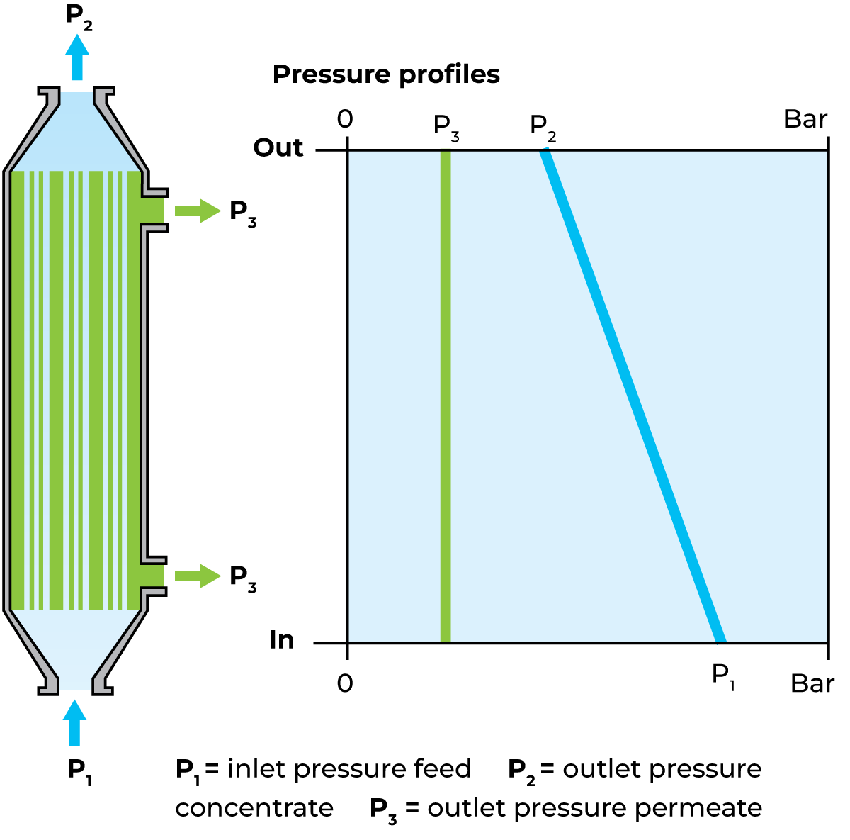
Fig. 7.4.14 Hydraulic (P2-P1) and transmembrane (P1+P2/2-P3) pressure drops over a membrane.
Principles of plant designs
The operation of membrane filtration plants mostly depends on the pressure generated by the pumps used. The following guides should be taken into consideration:
- The capacity of the pump(s) should match the required flow rate and the characteristics of the module(s), which vary widely according to module design and size.
- The pump(s) should be insensitive to changes in the viscosity of the processed stream up to the viscosity limit of the module. It/they should also operate efficiently at the temperatures used for processing and cleaning.
- The pump(s) must satisfy the sanitary standards for dairy equipment.
Several types of pumps are used, including centrifugal pumps and positive displacement pumps. Sanitary centrifugal pumps are normally used as feed and circulation pumps, but sanitary positive displacement pumps are occasionally used as high-pressure feed and circulation pumps for high-viscosity liquids, e.g. in the final stages of ultrafiltration of acidified milk.
Membrane separation plants can be used for both batch and continuous production. The feed solution must not contain coarse particles, which can damage the very thin filtration layer/active layer. For this reason, a fine-meshed strainer is often integrated into the feed system.
Processing temperature in membrane filtration applications
In most cases, the processing temperature is in the ranges of 10 – 20 °C or 50 – 55 °C for dairy applications, as temperatures in between are not favoured due to the risk of microbiology issues. Filtration systems are normally supplemented with a simple cooling system, integrated into the internal circulation loop. This is to compensate for the slight rise in temperature that occurs during operation due to the pump energy being absorbed into the product and to maintain a constant processing temperature.
Operation of membrane plants
Membrane filtration plants can be operated in both batch and continuous production. The latter is widely used in the dairy industry.
The feed solution must not contain coarse particles, which can damage the very thin filtration layer/active layer or get irreversibly stocked in the membrane spacer, thereby impairing the flow. For this reason, a fine-meshed strainer is often integrated into the feed system.
Batch production
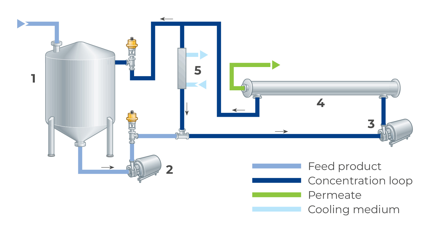
Fig. 7.4.15 Batch membrane filtration plant.
- Product tank
- Feed pump
- Circulation pump
- Membrane module
- Cooler
Systems for batch production (Figure 7.4.15) are mainly used for filtering small volumes of product, for example in laboratories and experimental plants. A certain amount of the product to be treated is kept in a buffer product tank. The product is circulated through the membrane system until the required concentration is obtained.
Continuous production
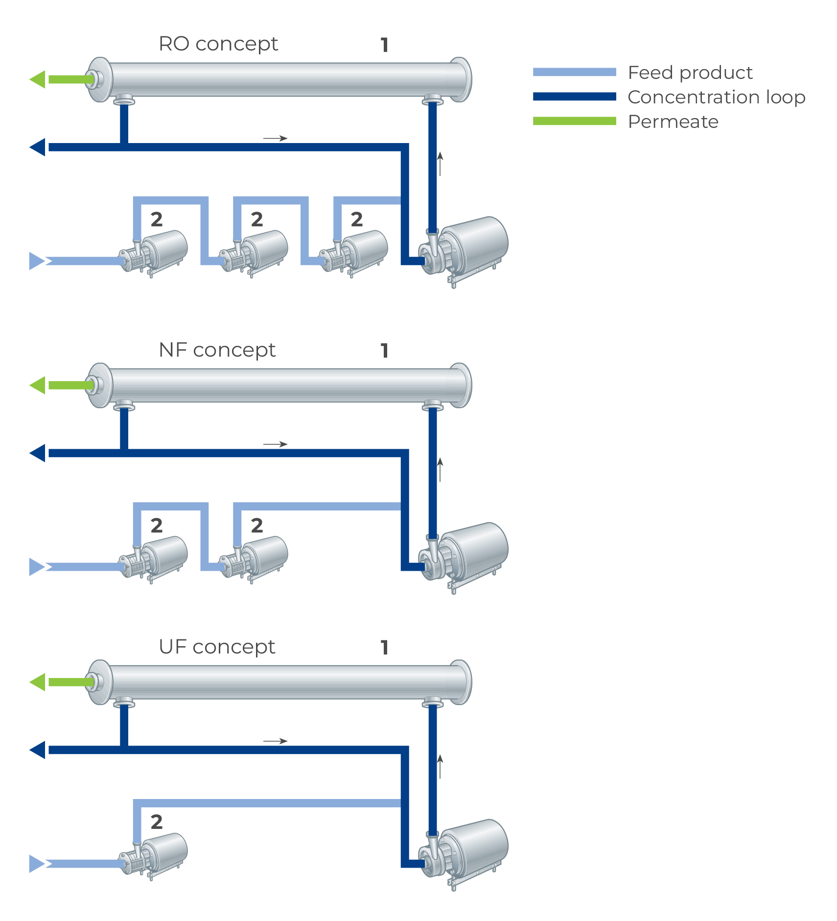
Fig. 7.4.16 Design principles for different filter loops.
- Membrane
- Cooler
Schematic designs of the membrane filtration system referred to are seen in Figures 7.4.16 and 7.4.17. The system illustrated in Figure 7.4.16 shows spiral-wound loop concepts for RO, NF, UF and MF applications with polymer membranes of different pore sizes, while Figure 7.4.17 shows an MF loop concept with ceramic membranes.
As the RO membranes are much tighter than those of the other systems, a higher inlet pressure is required for production. This is maintained by three sanitary centrifugal feed pumps in series and one sanitary centrifugal circulation pump.
The other filtration spiral-wound systems, NF, UF and MF, have more open membranes and can therefore be managed with two feed pumps and one feed pump, respectively. As was mentioned earlier, the ceramic MF concept is based on two filter modules operated in series in a filter loop system that also has one centrifugal pump for circulation of the retentate and one for circulation of the permeate.
The feed solution may be supplied from a separation plant with a system for constant pressure at the outlet, or from a balance tank equipped with a pump and a system for capacity regulation.
A continuous UF spiral-wound plant with 3 loops is illustrated in Figure 7.4.19. Figure 7.4.20 illustrates a continuous ceramic MF system in a line for bacteria and spore reduction in cheese milk.
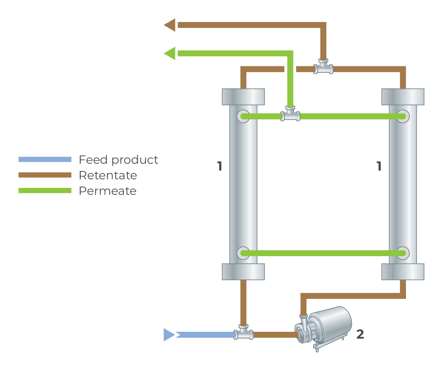
Fig. 7.4.17 Design principle of a MF filter loop.
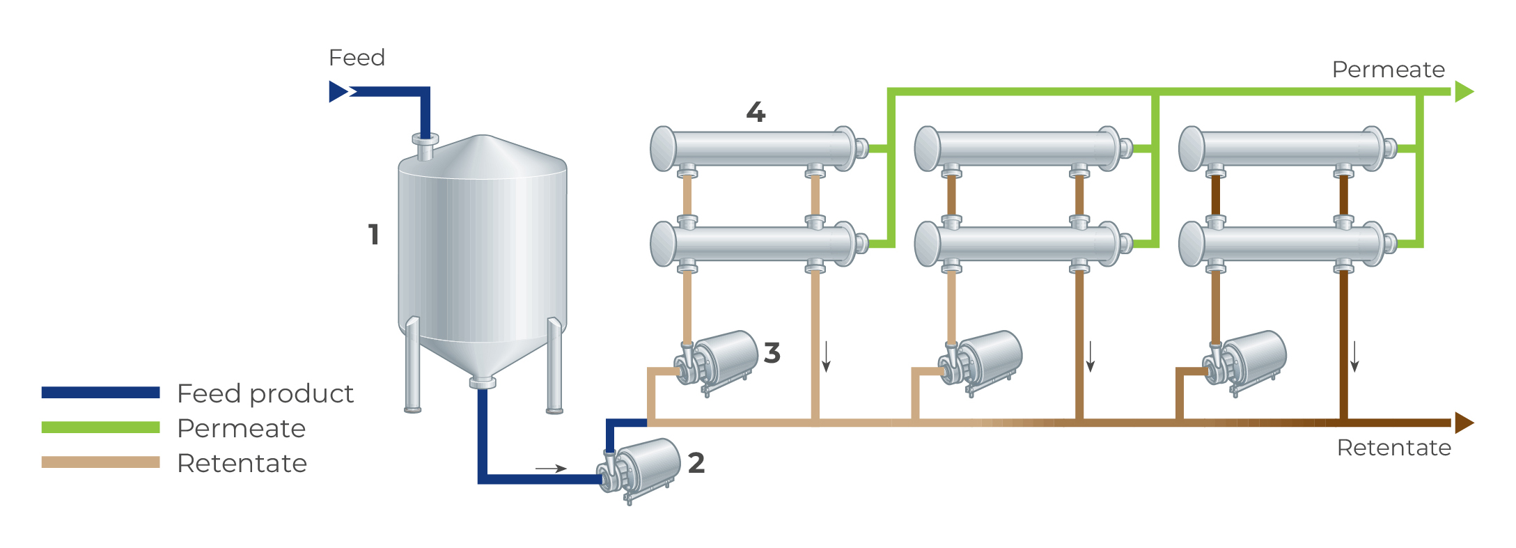
Fig. 7.4.19 A continuous UF spiral-wound plant with 3 loops
- Buffer tank
- Feed pump
- Loop pump
- Membrane
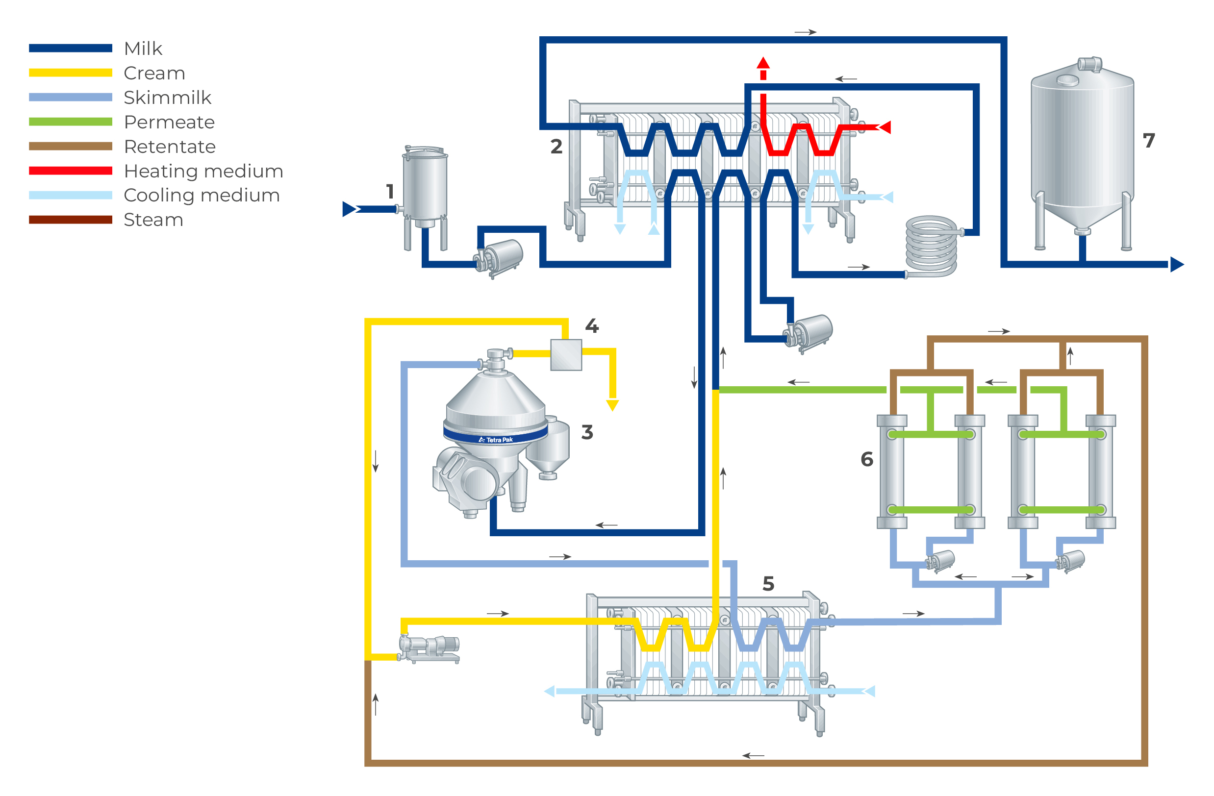
Fig. 7.4.20 a continuous ceramic MF system in a line for bacteria and spore reduction in cheese milk.
- Buffer tank
- Plate heat exchanger
- Separator
- Standardizer
- Cooler
- Ceramic MF membrane
- Storage tank