Designing a process line
In the dairy, raw milk passes through several stages of treatment in various types of processing equipment before reaching the consumer in the form of a finished, refined product. Production usually takes place continuously in a closed process, where the main components are connected by a system of pipes. The type of treatment involved and the design of the process depend on the end product.
In a dairy, raw milk passes through several stages of treatment in various types of processing equipment before reaching the consumer in the form of a finished, refined product. The equipment used for each stage is described in Chapter 7, where each sub-chapter focuses on an individual component. Production usually takes place continuously in a closed process, where the main components are connected by a system of pipes. The type of treatment involved, and the design of the process depend on the end product.
The process described in this chapter is general milk pasteurization. This process is the basic operation in market-milk processing and also constitutes an important pre-treatment stage in a chain of dairy processes such as cheesemaking and cultured milk production. The aim is to present some considerations the plant designer has to face when planning a milk processing plant.
Process design considerations
There are many aspects to be considered when a process line is designed. They can vary and be extremely complex, which places considerable demands on those responsible for the preliminary planning. Project engineering always involves a compromise between different requirements such as:
- Product-related – concerning the raw material, its treatment and the quality of the end product
- Process-related – concerning plant capacity, selection of components and their compatibility, degree of process control, availability of heating and cooling media, cleaning of processing equipment, etc.
- Economic – that the total cost of production to meet the stipulated quality standards is as low as possible
- Legal – legislation stipulating process parameters as well as choice of components and system solutions
The process illustrated in Figure 8.1.1 deals with heat treatment – pasteurization – of milk, e.g. market milk for sale to consumers.
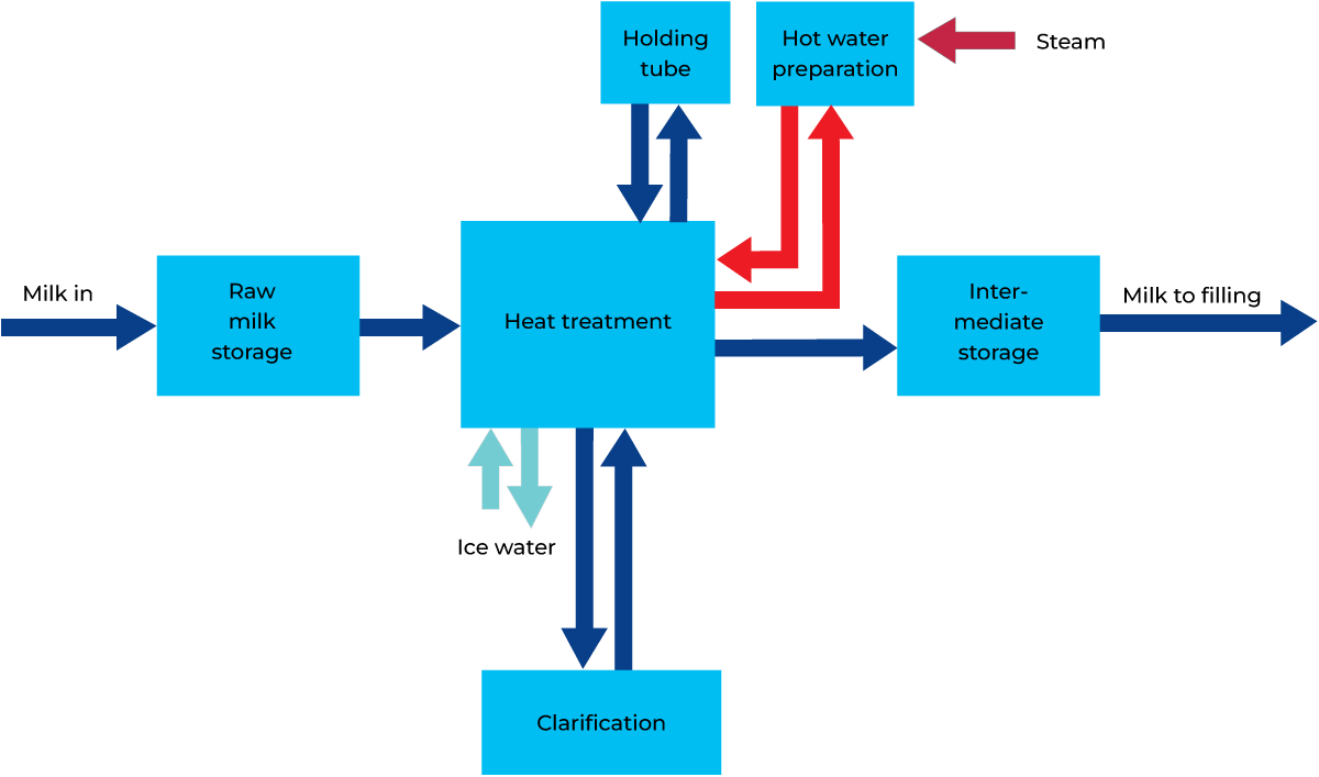
Fig. 8.1.1 Example of block chart of the milk pasteurization process.
Some legal requirements
In most countries where milk is processed into various products, certain requirements are determined by law to protect consumers against infection by pathogenic microorganisms. The wording and recommendations may vary, but the combination below covers the most commonly stated requirements:
Heat treatment
The milk must be heat treated so that all pathogenic microorganisms are killed. A minimum temperature/ holding time of 72 °C for 15 seconds must be achieved.
Recording
The heating temperature and holding time must be automatically recorded and the transcript saved for a prescribed period of time.
Clarification prior to heat treatment
As milk often contains solid matter such as dirt particles, leucocytes (white blood corpuscles) and somatic cells (of udder tissue), it must be clarified. Since pasteurization is less likely to be effective if bacteria are hidden in lumps and particles in the milk, clarification must take place before heating. Milk can be clarified in a filter or, more effectively, in a centrifuge (centrifugal clarifier or separator).
Preventing reinfection
Milk pasteurizers are calculated to maintain a higher pressure in the pasteurized milk flow compared to the unpasteurized milk and service media in the heat exchanger. If a leak should occur in the heat exchanger, pasteurized milk must flow into the unpasteurized milk or cooling medium, and not in the opposite direction. In order to ensure this, a booster pump to create a pressure differential, together with relevant pressure sensors, is often required and in certain countries it is mandatory. The system is referred to as “differential pressure supervision”.
In the event of failure to meet the requirement on heating temperature, holding time or differential pressure, the plant must be provided with a flow diversion valve to divert the insufficiently heated milk away from final product tanks. This is often done with a divert valve directing the milk back to the balance tank.
According to regulations set by the European Union, the heat treatment equipment must be approved or authorised by competent authority and at least fitted with:
- Automatic temperature control
- Recording thermometer
- Automatic safety device preventing insufficient heating
- Adequate safety system preventing the mixture of pasteurized milk with incompletely heated milk
- Automatic recording device for the safety system referred to in the preceding intent
Equipment required
The following equipment is required for a remote-controlled process:
- Silo tanks for storing the raw milk
- Storage of pasteurized milk
- Pasteurizing unit consisting of:
- Plate heat exchanger for heating and cooling
- Holding tube for holding the milk at pasteurization temperature
- Centrifugal clarifier (when only whole milk is to be treated, a centrifugal separator is not needed)
- General processing and control equipment:
- Pipes and fittings for connecting main components
- Pneumatically operated valves for controlling and distributing the product flow and cleaning fluids
- Pumps for transportation of milk and cleaning liquids
- Control equipment for control of capacity, pasteurization temperature, product pressure, valve positions, etc
- Various service systems:
- Water supply
- Steam or hot water supply
- Refrigeration for coolant
- Compressed air for pneumatically operated equipment
- Electric power
- Drain and wastewater collection
Most of the service systems are described in Chapter 7.11. Service media requirements are calculated after the plant design is agreed upon. Thus, the temperature program for pasteurization must be known, as well as the specifications for all other areas where heating and cooling are needed (cold storage, cleaning systems, etc.) before the number and power of electrically operated machines, number of pneumatically operated units, working hours of the plant, etc. can be determined. Such calculations are not presented in this book.
Choice of equipment
Raw milk silos
The number and size of the silo tanks are determined by the raw milk delivery schedules in relation to the production schedule of the dairy. Another factor when deciding this is the time that raw milk is allowed to stand in the silos before being processed. This in turn depends on the raw milk quality. In many dairies, the time limit is in the range of 24 – 48 hours. Preferably, the milk should have been stored for at least one hour before being processed to allow time for degassing of the milk in the silo.
Storage tanks for pasteurized milk
The number and size of tanks for pasteurized milk are determined by the production schedule. The pasteurizer capacity and running time must be matched with the filling machine operation. If milk with a different fat content is also made, then the number of tanks must be calculated to accommodate all types of milk that are produced in a day. If different milk qualities, for example, “standard” and “organic” milk, are produced on the same day, this will also require separate tanks to be available. If the dairy has a procedure for making quality checks for each tank before it is released for filling, there needs to be enough storage capacity to allow for the time it takes to make lab analyses and release the tanks for filling. Depending on all those considerations, the tank area for pasteurized milk can consist of a number of small tanks or a few large silos.
The complete pasteurizer
A milk pasteurizer, complete with equipment for operation, supervision and control of the process, is made using matching components, forming an integrated process unit, as in Figure 8.1.2.
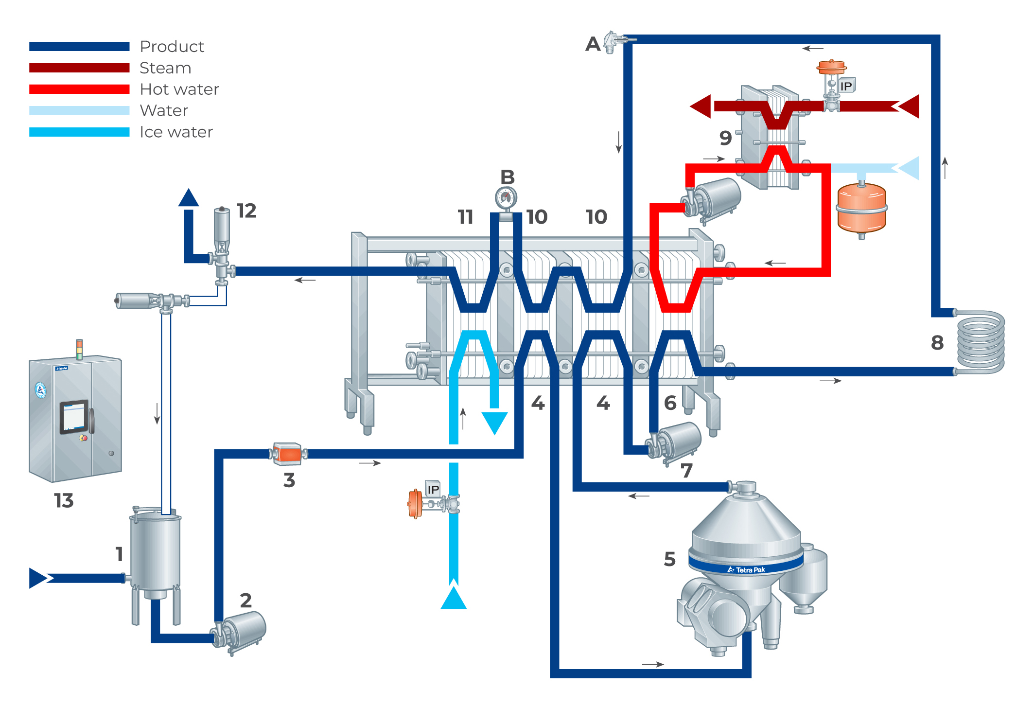
Fig. 8.1.2 The complete pasteurizer plant consists of:
A. Temperature indicator 4. Regenerative preheating sections 9. Hot water heating system
B. Pressure indicator 5. Centrifugal clarifier 10. Regenerative cooling sections
1. Balance tank 6. Heating section 11. Cooling section
2. Feed pump 7. Booster pump 12. Flow diversion valve
3. Flow transmitter 8. Holding tube 13. Control panel
Process parameters
The main aim of pasteurizing milk is to eliminate pathogenic microorganisms. To achieve this, the milk is heated to not less than 72 °C for at least 15 seconds. These parameters are stipulated by law in many countries. A plate heat exchanger is most common for milk pasteurization purposes.
When the relevant parameters are known, the size (dimensioning) of the heat exchanger can be calculated. In the present example, the parameters are:
- Plant capacity, l/h = 20 000
- Temperature programme, °C = 4 – 72 – 4
- Clarified temperature = 55 °C
- Regenerative effect, % = 90 – 94
- Temperature of the heating medium, °C = 74 – 75
- Temperature of the coolant, 2 °C
The demand for service media (steam, water and ice water) is also calculated, to enable the design of valves for steam regulation and ice water feed.
Balance tank
The inlet valve, or a speed signal to the supply pump, regulates the flow of milk to the pasteurizer and maintains a constant level in the balance tank. If the supply of milk is interrupted, the level will begin to drop.
As the pasteurizer must be full at all times during operation to prevent the product from burning onto the plates, the balance tank is often fitted with a low-level electrode which transmits a signal as soon as the level reaches the minimum point. This signal actuates the flow diversion valve, which returns the product to the balance tank. The milk is replaced by water and the pasteurizer shuts down when circulation has continued for a pre-determined time.
Feed pump
The feed pump supplies the pasteurizer with milk from the balance tank. A flow transmitter controls the feed pump speed to give a constant flow. This guarantees stable temperature control and a constant holding time for the required pasteurization effect.
Regenerative pre-heating
The cold untreated milk is pumped through the first section in the pasteurizer, the pre-heating section. Here, it is regeneratively heated with pasteurized milk, which is cooled at the same time.
If the milk is to be treated at a temperature between the inlet and outlet temperatures of the regenerative section, for example, clarification at 55 °C, the regenerative section is divided into two sections. The first section is dimensioned so that the milk leaves at the required temperature of 55 °C. After being clarified, the milk returns to the pasteurizer, which completes the regenerative pre-heating in the second section.
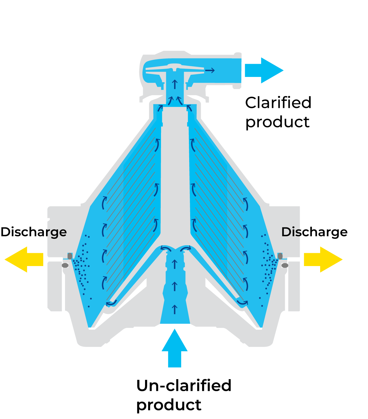
Fig. 8.1.3 Bowl of a centrifugal clarifier
Centrifugal clarifier
As the milk in the present example is not going to be separated into skim milk and cream, a centrifugal clarifier is shown in Figure 8.1.3.
Some dairies specify centrifugal clarification of cold (<6 °C) raw milk immediately after arrival at the dairy, especially when the milk is going to be stored until the next day. However, clarification at about 55 °C is much more efficient, because the viscosity of the milk is lower at that temperature.
The milk feeding the clarifier is therefore taken from the first regenerative heating section at 55 °C.
Booster pump to prevent reinfection
Care must be taken to avoid any risk of contamination of the pasteurized product by unpasteurized product or cooling medium. If any leakage should occur in the pasteurizer, it must be in the direction from pasteurized product to unpasteurized product or cooling medium.
This means the pasteurized product must be under higher pressure than the medium on the other side of the heat exchanger plates. In Figure 8.1.2, a booster pump (7) is there fore installed in the product line before the heating section. It can also be installed after the heating section. The first position minimises the operating temperature of the pump and prolongs its lifetime. The pump increases the pressure and maintains a positive differential pressure on the pasteurized product side, throughout the regenerative and cooling sections of the pasteurizer. Installation of a booster pump is specified in the legal requirements for pasteurization in some countries.
The regenerative energy-saving effect in a milk pasteurizer is typically between 90 and 94%
Hot water heating systems
The final heating of the milk to pasteurization temperature is done with hot water. Water temperature is 1 – 3 °C above milk pasteurization temperature. Heating media is supplied by the utility central. It can be either hot water or steam. Figure 8.1.4 shows a hot water system where the utility central is supplying steam to the process area.
The hot water system in Figure 8.1.4 is a closed system consisting of a compact cassette-type plate heat exchanger (3) equipped with a steam regulating valve (2) and a steam trap (4).
The hot water is circulated by the centrifugal pump (5) via the heater (3) and the heating section of the pasteurizer.
The function of the expansion vessel (7) is to compensate for the increase in the volume of the water that takes place when it is heated. The system also includes pressure and temperature indicators as well as safety and ventilation valves (8).
Temperature control
A constant pasteurization temperature is maintained by a temperature controller acting on the steam regulating valve (2) in Figure 8.1.4. Any tendency for the product temperature to drop is immediately detected by a sensor in the product line before the holding tube. The sensor then changes the signal to the controller, which opens the steam-regulating valve to supply more steam to the water. This increases the temperature of the circulating water and stops the temperature drop in the product.
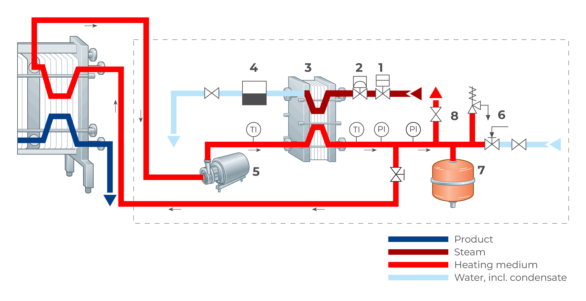
Fig. 8.1.4 Principle of the hot water system connected to a pasteurizer.
1. Steam shut-off valve. 6. Water regulating valve
2. Steam regulating valve 7. Expansion vessel
3. Heat exchanger 8. Safety and ventilation valves
4. Steam trap T1 - Temperature indicator
5. Centrifugal pump P1 - Pressure indicator
Holding tube
The length and size of the externally located holding tube is calculated according to the required holding time and hourly capacity of the plant. Dimensioning data for the holding tube are given in Chapter 7.1. Typically, the holding tube is covered by a stainless steel hood to prevent temperature drop, and also to protect people from getting burned when touching it.
Before the holding cell, there is a temperature transmitter that sends a signal to the steam or hot water valve to provide the correct pasteurization temperature.
Divert control
It is essential that the milk has been properly pasteurized before it leaves the plate heat exchanger. If the temperature drops below 72 °C, the unpasteurized milk must be kept apart from the already pasteurized product. To accomplish this, a temperature transmitter and flow diversion valve are fitted in the pipe downstream of the holding tube. The valve (3) in Figure 8.1.5 returns unpasteurized milk to the balance tank if the temperature transmitter detects that the milk passing it has not been sufficiently heated.
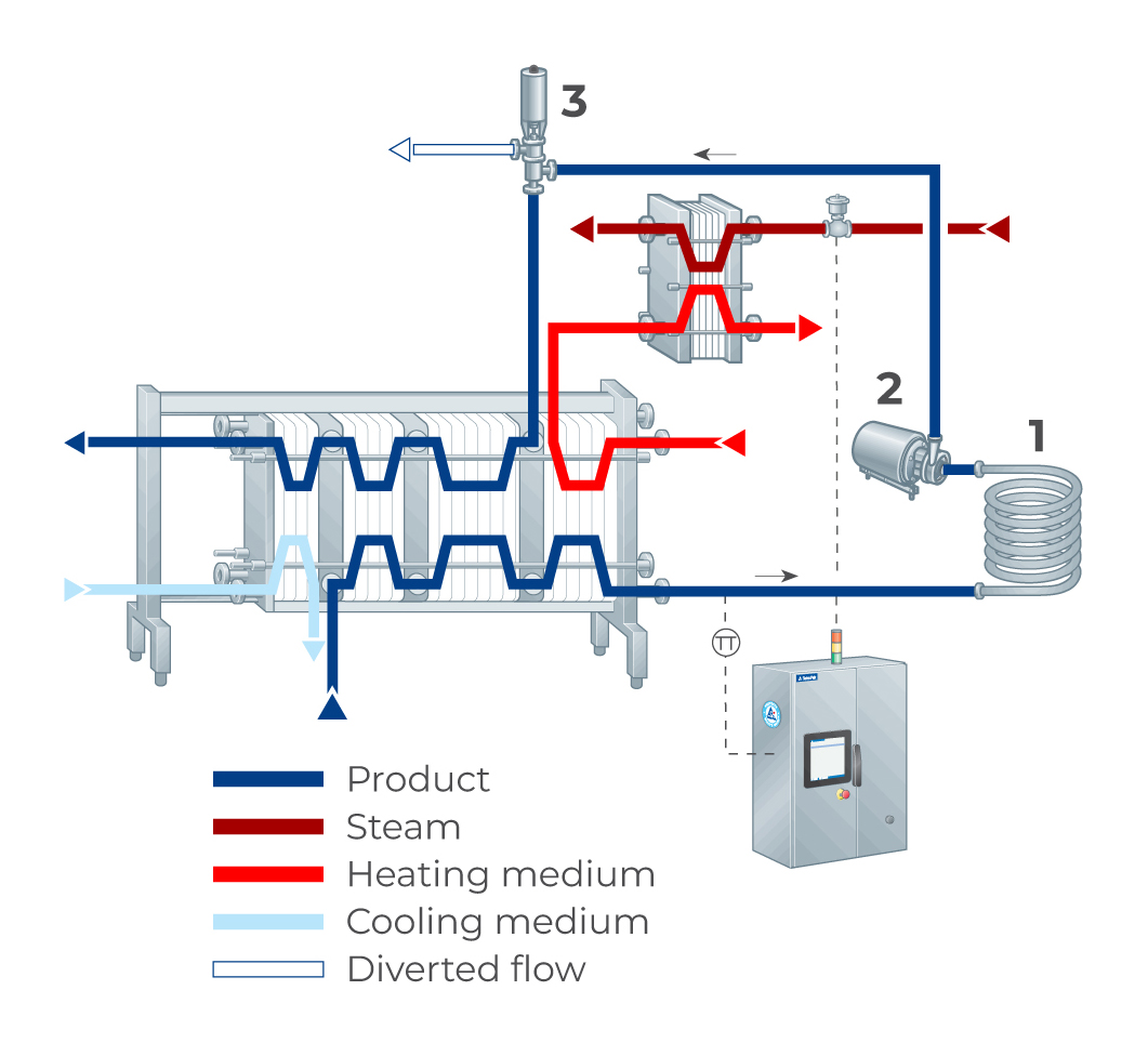
Fig. 8.1.5 Automatic temperature control loop.
TT Temperature transmitter
1. Holding tube
2. Booster pump
3. Diversion valve
The position of the flow diversion valve is recorded together with the pasteurization temperature. For the location of the flow diversion valve, various solutions are available to satisfy local regulations and recommendations. Below are two alternatives which are commonly utilised:
- The flow diversion valve is located just after the holding cell. If the temperature drops, the flow is diverted back to the balance tank to ensure that no unpasteurized milk reaches the parts downstream from the holding cell. Once the pasteurization temperature is restored, the pasteurizer can resume production.
- The flow diversion valve is located after the cooling section of the plant. Following a temperature drop, the flow is diverted to the balance tank and the plant is emptied of product, cleaned and sanitised. The plant is then ready for restart when the temperature conditions are acceptable again.
Cooling system
After the holding section, the milk is returned to the regenerative section(s) for cooling. Here the pasteurized milk transfers its heat to the cold incoming milk. The outgoing pasteurized milk is then chilled with cold water, ice water, a glycol solution or some other refrigerant, depending on the required temperature. Chilling the milk to 4 °C for storage requires a final cooling step with a cooling medium at about 2 °C below the required milk outlet temperature. Ice water can only be used if the final temperature is above 3 – 4 °C.
The coolant is circulated from the dairy refrigeration plant to the point of use, as shown in Figure 8.1.6. The flow of coolant to the pasteurizer cooling section is controlled to maintain a constant product outlet temperature. This is done by a regulating circuit consisting of a temperature transmitter in the outgoing product line, a temperature controller in the control panel and a regulating valve in the coolant supply line.
The temperature of the chilled milk is normally recorded, together with the pasteurization temperature and the position of the flow diversion valve. The graph consequently shows three curves.
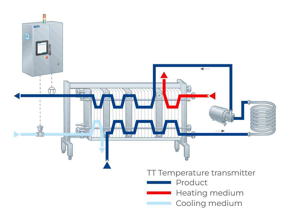
Fig. 8.1.6 Principle of the cooling system for a pasteurizer
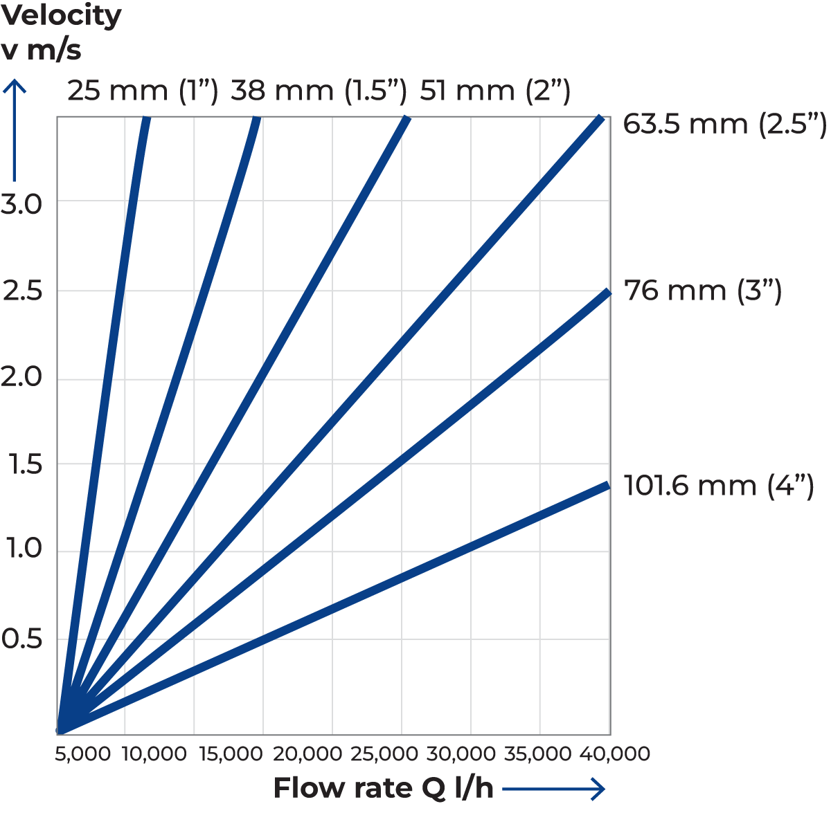
Fig. 8.1.7 Product velocity and flow rate graph.
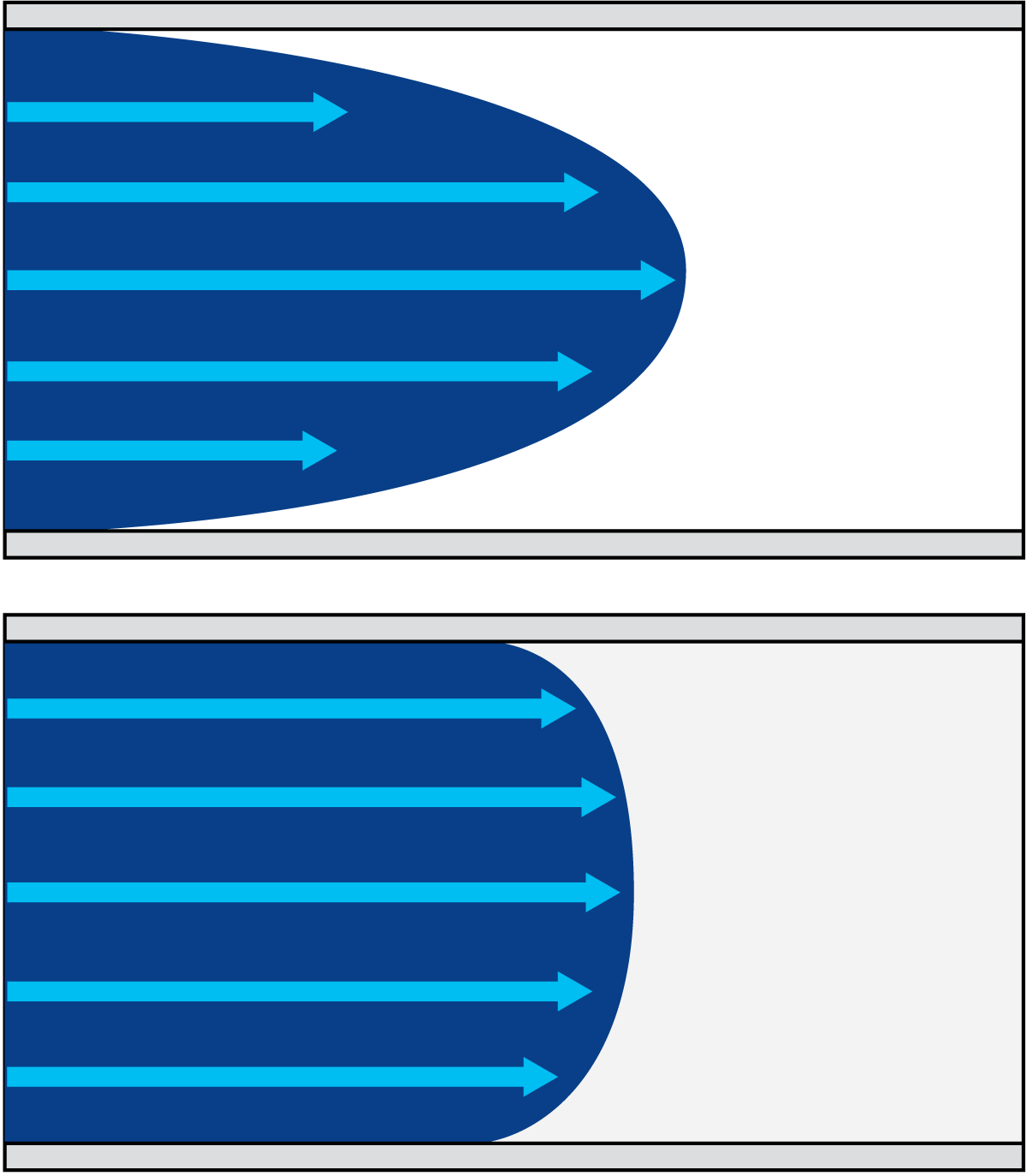
Fig. 8.1.8 Velocity profile diagrams for laminar and turbulent flows.
Design of piping system
In the example in this chapter, 20,000 litres of milk per hour have to pass through pipes, fittings and processing equipment during production. The product velocity through the pipes is determined by
the size of the passage, i.e. the inside diameter of the pipe. The larger the diameter, the lower the product velocity. For a flow rate of 20,000 litres per hour, the product velocity in a 76 mm (3") pipe will be 1.25 m/s. The velocity will be 2.75 m/s if a 51 mm (2") pipe is selected.
Higher velocities result in greater friction in the liquid itself and between the liquid and the pipe wall. Consequently, there is more mechanical treatment of the product. For each product, there is an upper velocity limit that should not be exceeded if quality demands are to be met. For milk, this velocity is about 3 m/s.
It might then seem reasonable to choose a larger pipe size than the minimum required by velocity considerations, but larger pipes mean larger components and increased costs. This will also result in larger mix phases and product losses. The diameter nearest the limit should therefore be chosen. In our case, this is 63.5 mm (2.5"), which corresponds to a velocity of 1.75 m/s, as shown in Figure 8.1.7.
Laminar and turbulent flows
Laminar flow is a type of flow in which the particles maintain a continuous, steady motion along parallel paths. This type of flow occurs, for example, in straight, round pipes or between parallel walls at low velocities.
In turbulent flow, the particles have an irregular motion and intermix intensively with each other. The length of a line represents the mean velocity of the particles at various points in the section through the passage, as illustrated in Figure 8.1.8. In laminar flow, the velocity is greatest at the centre of the passage. Due to the friction between the layers, the velocity slows progressively towards the walls, where it is zero.
In turbulent flow, the layers intermix and therefore the velocity of the liquid is roughly the same in the central part of the passage but drops rapidly towards the walls. On the walls, a very thin laminar layer of the liquid has zero instantaneous velocity.
To obtain laminar flow in a round pipe, the diameter must be small, the velocity low and/or the viscosity of the liquid high. When designing a holding tube for legal pasteurization it is necessary to know if the flow is turbulent or laminar to ensure enough holding time for all the milk.
Pressure drop
The flow resistance of a liquid in a component results in a loss of pressure. If the pressure is measured with a pressure gauge (Figure 8.1.9) before and after the component, the pressure will be lower on the discharge side. The component, for instance a shut-off valve, causes a pressure drop in the line. This pressure drop is equivalent to the resistance in the component. The magnitude depends on the velocity, i.e. the flow rate and the size of the pipes.
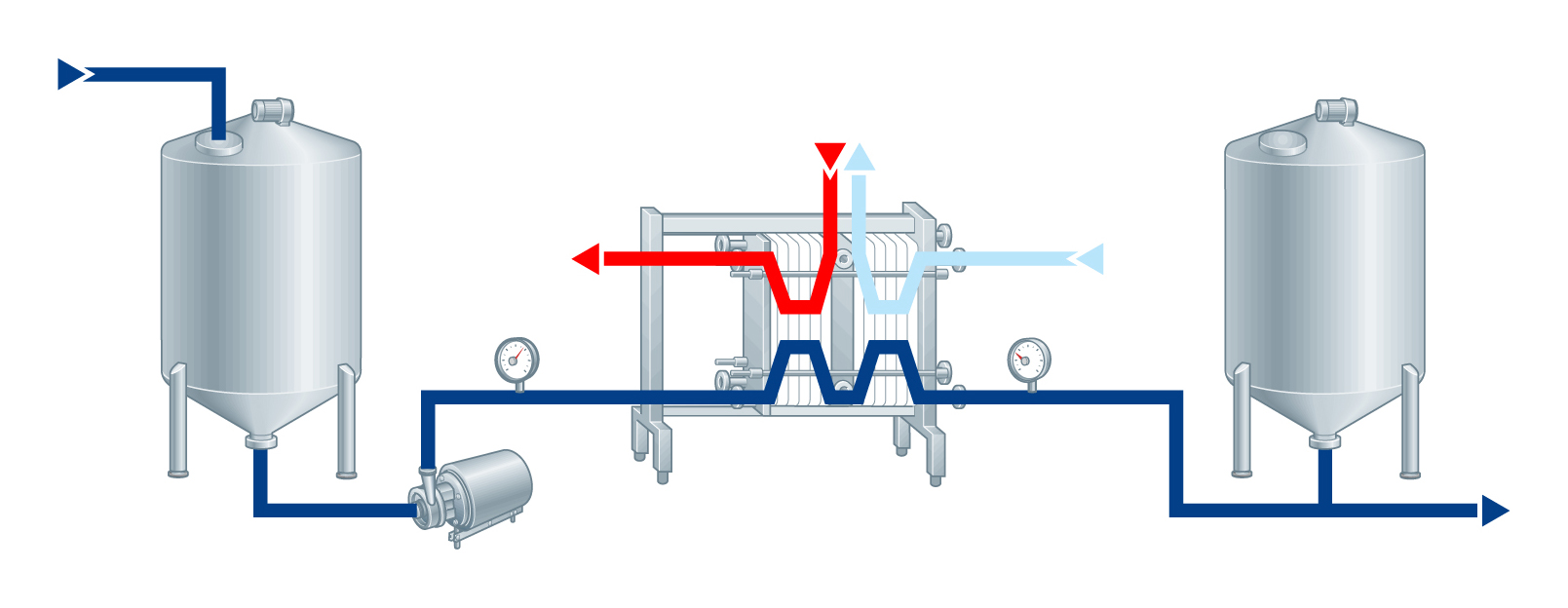
Fig. 8.1.9 Pressure drop can be shown by pressure in the process line.
The pressure drop of a component is given in bar or kPa. It can also be often stated as the loss of head in metres for different flow rates. The graph in Figure 8.1.10 covers flow rates from 5,000 litres/hour for the smallest pipe diameter, 1.5" (38 mm), to 200,000 litres/ hour for the largest, 4" (101.6 mm) shut-off valve.
For a flow rate of 20,000 litres/hour and a pipe size of 2.5" (63.5 mm), a velocity of 1.75 m/s, the graph indicates a pressure drop, or loss of head, of 0.4 metres over the fully open valve.
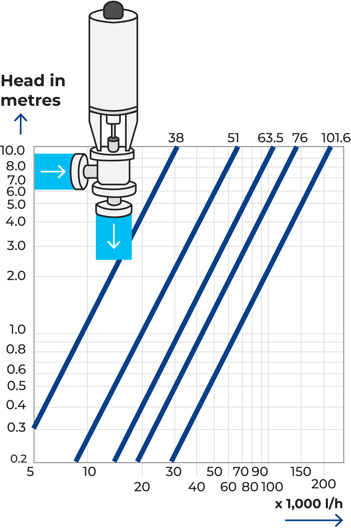
Fig. 8.1.10 Pressure-drop graph for a shut-off valve.
The pressure drop over each of the components in the line for a given flow rate can be determined in the same way. When added together, these values give the total pressure drop for the system. Every component in the line should be dimensioned to cause the lowest possible pressure drop. A pressure drop involves an increase in flow velocity, either in the form of turbulence or by local acceleration through passages
Higher velocities result in increased friction at the surfaces of the pipe and other equipment and greater forces in bends, etc. This increases the mechanical treatment of the product.
In the case of milk, this may lead to breakage of the fat globules, exposing the released fat to attack by lipase enzymes. Eventually, the resulting high content of free fatty acids adversely affects the flavour of the milk. This problem is aggravated if air is present during the mechanical treatment of the product. This can occur if air is sucked in through leaking unions. For other products, such as yoghurt, the treatment of the product must be particularly gentle. The greatest care must be taken in the selection of components as well as in the dimensioning and design of the process line.
The size of the pipes in a system must be such that the velocity of the liquid does not exceed the critical value for the product (3 m/s for milk, or slower for some other dairy products). The number of valves in the line should be kept to a minimum and the pressure drops across them should be as low as possible. They should also be placed so that unnecessary changes of direction are avoided.
Process control equipment
To ensure trouble-free operation of the process and achieve the desired product quality, it is necessary to control quantities such as liquid levels, flows, temperatures, pressures, concentrations and pH values at certain pre-determined levels. The equipment for measuring and controlling these parameters includes various types of sensors, transmitters, actuators and control equipment.
A sensor is an element which measures an actual quantity. A transmitter converts the signal from the sensor to a standardised signal. This value is also known as the measured value. Often sensors and transmitters are combined in one measuring device, also called a transmitter, for example, a pressure transmitter. Design and functionality vary according to requirements. Examples of measuring devices are temperature, level, pressure and conductivity transmitters.
A regulating device is essentially an adjusting mechanism, such as a regulating valve or a pump with variable speed, fitted in a process line. The setting of the regulating device, valve plug position or motor speed, determines the amount of the regulated process parameters.
A regulator calculates the difference between the measured value and the set value and based on that difference, adjusts the signal to the regulating device.
If the measured value changes, the signal from the transmitter changes accordingly. When the measured value does not equal the set value, the regulator adjusts the signal to the regulating device. As a result, the position of the regulating device is adjusted (valve position or speed) to match. The transmitter immediately senses the change in process parameters and transmits this information to the regulator. This cycle of comparison and correction, the control loop, is repeated until the set and measured values match. A control loop is illustrated in Figure 8.1.11.
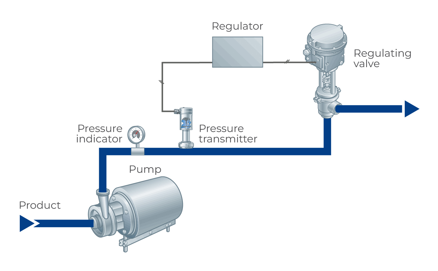
Fig. 8.1.11 Control loop for pressure control, consisting of a transmitter, a regulator and a regulating valve.
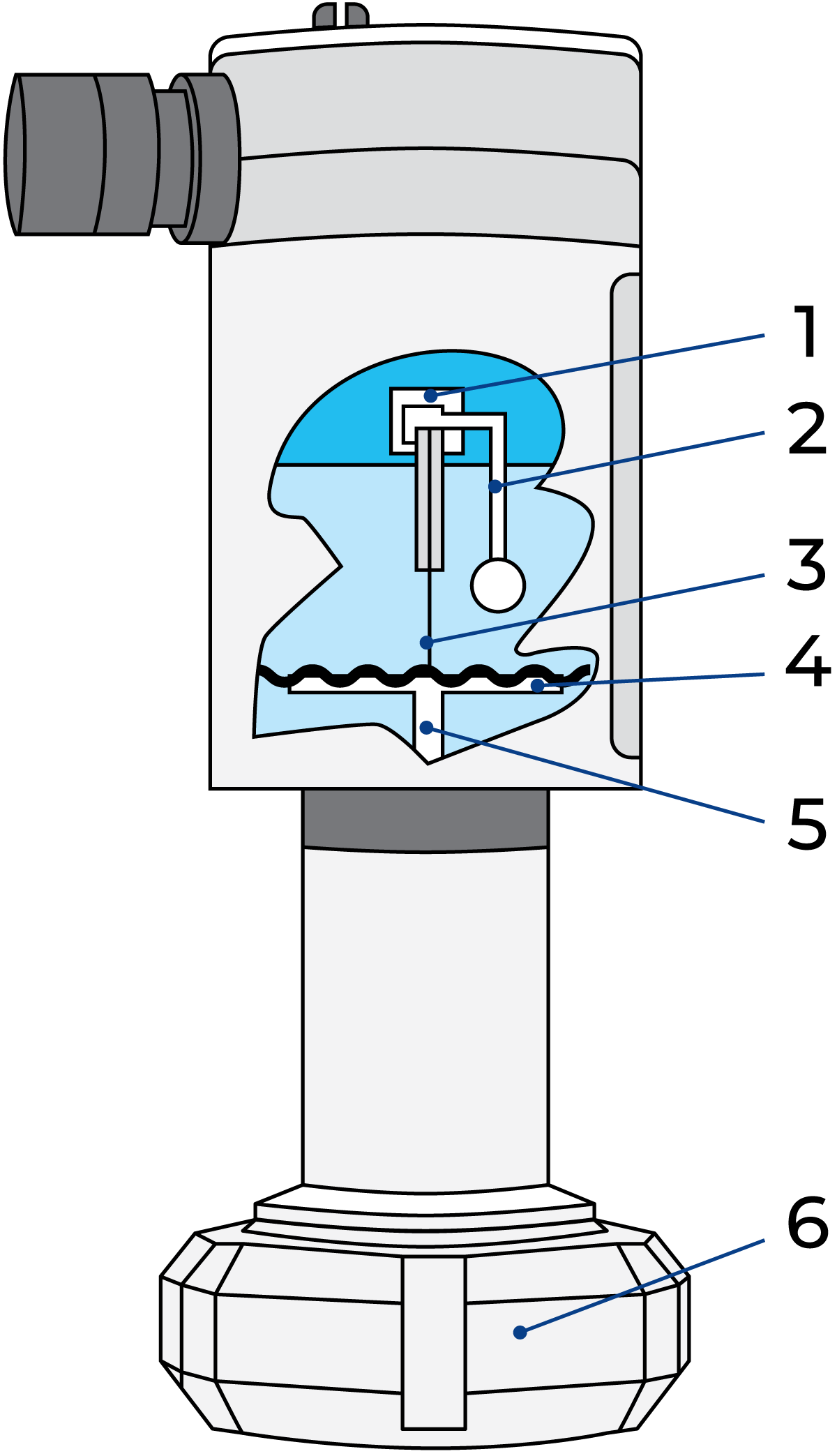
Fig. 8.1.12 Pressure transmitter
1. Sensor
2. Reference pressure
3. Capillary pipe
4. Membrane
5. Process pressure
6. Nut
Transmitters
Transmitters in control systems vary considerably in design and function. Some transmitters react directly to changes in the measured value. In the pressure transmitter in Figure 8.1.12, the pressure of the product on a membrane is transferred to the sensor and a transmitter, which gives an electrical signal directly proportional to the product pressure.
Most transmitters, however, operate indirectly. They measure the changes in a physical quantity, which has a constant relation to the process parameters to be controlled. This type of transmitter was shown previously in connection with the transport of liquid through the line, where a required flow rate is maintained by controlling the pressure of the product at the pump outlet.
The above-mentioned pressure transmitter can also be used to measure the level in a tank. Installed in the bottom of a tank, it senses the static pressure of the liquid column above the diaphragm. This pressure is proportional to the height of the liquid. A signal is transmitted to an instrument, which indicates the level.
Many types of transmitters utilise the fact that the electrical resistance of metals varies with temperature in a characteristic manner. One such transmitter is the common temperature transmitter, Figure 8.1.13. A wire of platinum is mounted in a protective tube, which is inserted in the line so that it is heated by the liquid.
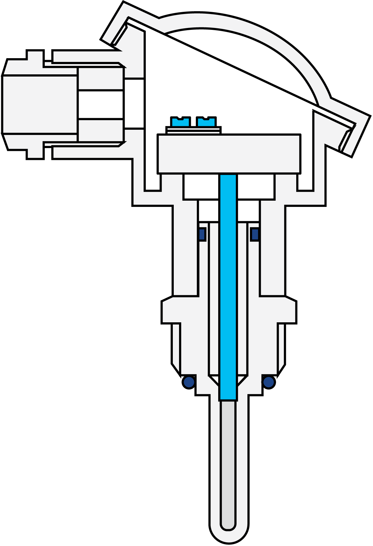
Fig. 8.1.13 Resistance type temperature transmitter
The resistance can be measured by connecting the metal wire to an electrical circuit. Any change in the resistance will correspond to a given change in temperature, and the temperature of the product can therefore be determined. The transmitters described above are the ones most often used in dairies. There are, however, many other types available on the market.
Regulators
The regulator in Figure 8.1.14 is the brain of the temperature control system and the controller is available in many different forms. According to a previous definition, a regulator is a device that continuously compares the measured value with a reference or pre-set (set point) value. Any differential causes the regulator to transmit a corrective signal to the regulating unit, which then adjusts its setting accordingly. The corrective process continues until the measured value and the set point value coincide again.
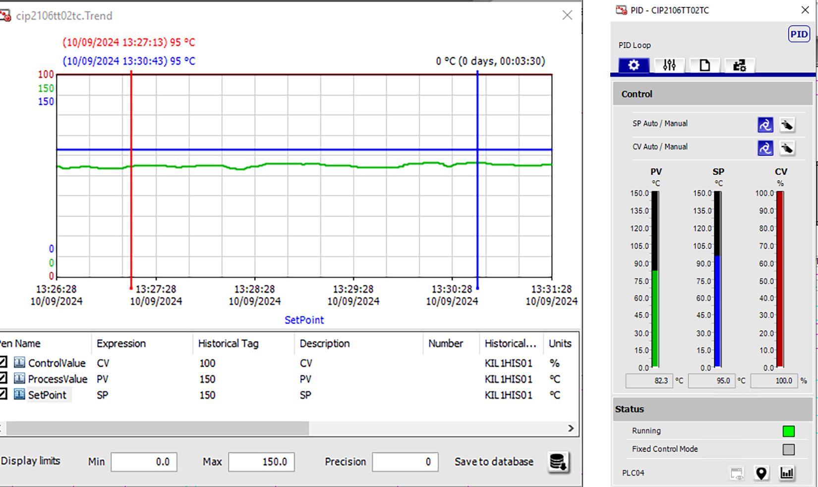
Fig. 8.1.14 Regulator
The regulator may be a local electronic regulator or built into the control system as a software regulator. On electronic controllers, there is a knob for setting the required set point, which is indicated by an indicator on a scale. The measured value, the output from the transmitter, can be read on the scale at all times. There is also a scale showing the output signal to the regulating device.
Nowadays, most regulators are based on software in the control system. The regulator is displayed on the operator station as a graphical representation of the electronic regulator, with process value, set point and output signal. These parameters are also displayed as trend curves, which can assist the operator when working with the regulating system.
Some regulators have a switch function, which can be used to produce a signal at a given maximum or minimum value. This signal can be used to perform a change in the process. An example is to re-circulate the flow of a pasteurizer if the temperature at the outlet of the heat exchanger holding section drops below 72 ºC. The switch is set to operate at this temperature and as soon as the temperature drops under this value it will close the solenoid valve controlling the air supply to the flow diversion valve, thereby forcing the pasteurizer to re-circulate the product.
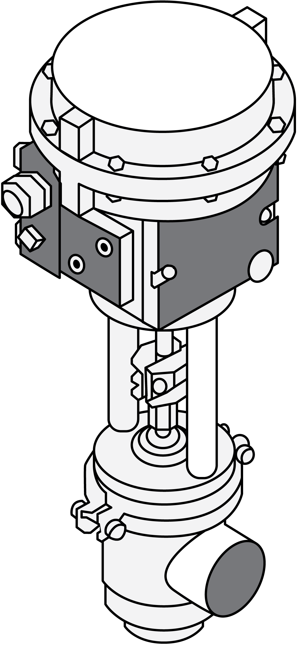
Fig. 8.1.15 Regulating valve
The regulating device
A pneumatic regulating valve, shown in Figure 8.1.15, is built around a body with a seat for the plug, which is attached to the lower end of the regulating stem. The stem is operated between the open and closed positions by differential pressure between the upper and lower sides of the piston. When the pressure is higher on the lower side, the piston moves upwards, lifting the plug from its seat. A higher pressure on top of the piston closes the valve.
Actuation is essentially as follows: a pneumatic signal from a controller is supplied to a proportioning device, a positioner, at the top of the valve. The positioner ensures that the position of the plug, in relation to the seat, is always proportional to the regulating signal. When the signal corresponds to the pre-set value, the positioner balances the pressures on either side of the piston so that the position of the plug remains constant. In this balanced condition, the pressure drop over the valve is exactly what is required, and the measured value registered by the transmitter coincides with the pre-set value.
If the product pressure drops, the transmitter reduces its signal to the regulator. As the measured value now no longer coincides with the pre-set value, the regulator reacts by increasing its signal to the valve actuator. The positioner then increases the pressure on the upper side of the piston, moving the plug towards the seat. The resulting increase in the valve flow resistance increases the product pressure and the reverse cycle of operations is initiated, retarding the downward movement of the piston.
A pneumatic regulating valve, shown in Figure 7.16, is built around a body with a seat for the plug, which is attached to the lower end of the regulating stem. The stem is operated between the open and closed positions by differential pressure between the upper and lower sides of the piston. When the pressure is higher on the lower side, the piston moves upwards, lifting the plug from its seat. A higher pressure on top of the piston closes the valve.
Actuation is essentially as follows: a pneumatic signal from a controller is supplied to a proportioning device, a positioner, at the top of the valve. The positioner ensures that the position of the plug, in relation to the seat, always is proportional to the regulating signal. When the signal corresponds to the pre-set value, the positioner balances the pressures on either side of the piston so that the position of the plug remains constant. In this balanced condition the pressure drop over the valve is exactly what is required, and the measured value registered by the transmitter coincides with the pre-set value.
If the product pressure drops, the transmitter reduces its signal to the regulator. As the measured value now no longer coincides with the pre-set value, the regulator reacts by increasing its signal to the valve actuator. The positioner then increases the pressure on the upper side of the piston, moving the plug towards the seat. The resulting increase in the valve flow resistance increases the product pressure and the reverse cycle of operations is initiated, retarding the downward movement of the piston.
When the pressure in the line has reached the pre-set value, the positioner again holds the valve piston in balance.